SincpacC3D
General Information
Command Summary

CreateAlignsFromPolylines
|
SincpacC3D
General Information
Command Summary
CreateAlignsFromPolylines |
Description
The CreateAlignsFromPolylines command creates Alignments and Profiles from a variety of objects, including polylines, 3D-Polylines, Feature Lines, and Survey Figures. Various pruning options may be used when creating the Alignment and Profile. In addition offset alignments and profiles from surfaces may be created at the time of conversion.
This command may be used to create both a Profile and Alignment simultaneously, or to create only an Alignment, or to add a Profile to an existing Alignment. In addition offset alignments and profiles maybe created. In any case, the source object is a 3D-Polyline or other linear object, and all pruning options may be used.
This command contains options for pruning the source linework in both the horizontal and vertical directions. These pruning options are applied completely independently of each other. So a point that is pruned from the alignment may still appear in the profile, and vice-versa.
Unfortunately, because of the built-in pruning employed by this command, a feature line that contains arc segments will lose its arcs with this command. If you may want to try the CAPFeature command instead. Also, this command processes standard polylines differently, in order to avoid losing the curves. However, because of this, the horizontal pruning and "Add Curves" options are disabled when creating Alignments/Profiles from standard polylines.
Usage
Run the CreateAlignsFromPolylines command and select the desired settings in the dialog box. Then select the 3D-Polylines or other objects to use for creating the alignments and/or profiles. The following dialog box will then appear:
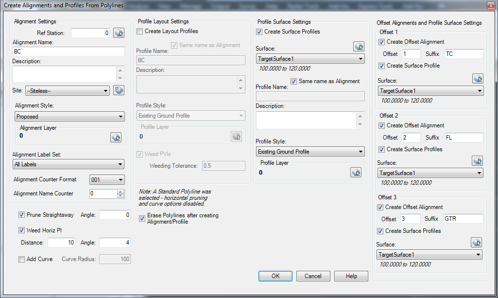
On the left side of the dialog, you may choose to either use the linework to create a profile on an existing alignment (if one exists), or you may create a new alignment. If you are creating a new alignment, the "Create Profile" checkbox will be available to you on the right side of the dialog box. So this command may be used to create both an alignment and profile, or create only an alignment, or create only a profile. The alignment counter format and alignment name counter increments the names of the alignments created to prevent duplicate names.
On the right side of the dialog box select the number of offsets to be created. The direction of the offset is relative to the direction of the object being created from an alignment. A target surface maybe created from a different surface for each offset alignment. The suffix will be included in the offset alignment's name. The format of the offset alignment name will be the base alignment, offset distance, suffix, and then the alignment counter.
Once you have all settings the way you want them, hit OK. The alignments and profiles will be created. If the erase polylines after creation check box is selected the original objects will be deleted.
Here is a brief description of the options available in this dialog box:
Ref Station: Enter the reference station for the alignment, with no station marks, i.e. for Station 10+00, enter "1000". Click on the little button next to the reference station if you wish to pick a point on-screen, or by default, the reference station is at the start of the alignment.
Prune Straightaways: When selected, this option removes PIs that are on-line between the PIs on either side.
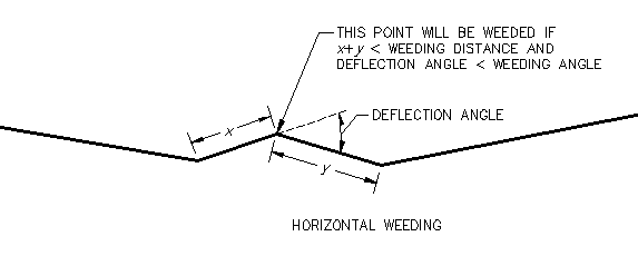
Weed Horiz PIs: Extra weeding factors for removing PIs. The PIs are examined from first to last in groups of three. If the overall distance (x+y in the diagram below) is less than the weeding distance, and the deflection angle is less than the weeding angle, then the middle point is pruned. Then the comparison is repeated for the next group of three points.
Add Curves to Alignment: When checked, a floating curve of the specified radius is added to each vertex, if it will fit.
Weed PVIs: When selected, this option will remove as many PVIs as possible, yet still end up with a resulting Profile that is within the specified tolerance at all points. For example, a value of 0.5' for this setting would result in a Profile that had as few PVIs as possible, but is within 0.5' of the source linework at all points along the Profile.
Erase Polylines: This option will remove the source objects from the drawing.
Create Offset Alignment: This option will create an offset alignment.
Offset: This option specifies the offset distance from the base created alignment. The offset values are not additive.
Usage: The command is originally intended to assist in the modelling of curb and gutter for a parking lots. A base surface representing the flow of the parking lot would be created. Offset alignments are created from the source object and then surface are sampled for the elevation of a various surface. The surfaces are intended to represent the Back of Curb, Top of Curb, Flowline, and Edge of Gutter. Dynamic AutoFeatureLines may then be created utilizing the Civil 3D command to create featurelines. The featurelines may then be added to a surface. The surfaces, profiles, and autofeaturelines are then dynamic and will update the design surface based on updates to the base surface.
See Also
CAPFeature is "Create Alignment and Profile from Feature Line". Creates an alignment and profile from an existing Feature Line or Survey Figure. Excess PVIs may also be pruned with a setting similar to the one in CAPSurface.
Creates an alignment and profile from an existing polyline and an existing surface. The surface is sampled at the specified interval, and/or at enough intervals to keep the error within a specified tolerance.
Add a lowering to an existing finish ground profile. Particularly useful for waterlines.
Creates alignments from polylines. Arcs in the polyline are converted to Free Curves, if possible.
Display Points by Station and Offset, as measured along an Alignment. Results are displayed on screen and may also be written to a file.
Prune PVIs from a Finished Ground profile.
Convert an Existing Ground profile (sampled from a surface) to a Finish Grade profile (with editable geometry points).
