SincpacC3D
General Information
Command Summary

CAPFeature
|
SincpacC3D
General Information
Command Summary
CAPFeature |
Description
The CAPFeature command creates an Alignment and Profile from a Feature Lines, and Survey Figures. Any curves in the Feature Line are maintained as curves in the Alignment. This command also contains an optional PVI pruning function similar to that found in the CAPSurface command.
Usage
Run the CAPFeature command and select the desired settings in the dialog box. Then select the 3D-Polyline or other object to use for creating the alignment and/or profile. The following dialog box will then appear:
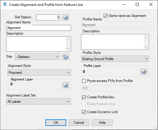
The left side of the dialog contains the settings for the alignment, and the right side contains the settings for the profile, including the option to link the new ALognment and Profile to the Featureline so any edits to the Featureline will be reflected in the Alignment/Profile. Once you have all settings the way you want them, hit OK. You will then be prompted to select a location for a Profile View. If you select a location, then you will see the Create Profile View dialog box. Or, you may right-click or hit the ESC key to skip the Profile View generation.
Unfortunately, it is difficult to have any control over the labels that appear on the Profiles in Profile Views. See the notes about the issues with Profile Labels in Profile Views for details.
When the option to "Prune excess PVIs from Profile" is selected, as many vertical PVIs will be removed from the Feature Line as possible. The resulting Profile will be within the specified tolerance of the source Feature Line at all points.
Example
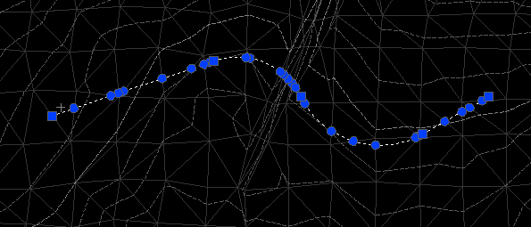
The example below shows a Feature Line. When the Feature Line was created, elevations were sampled from the Surface. The Feature Line has been selected in the image below, and you can see all the horizontal and vertical PIs in the Feature Line indicated by blue dots.
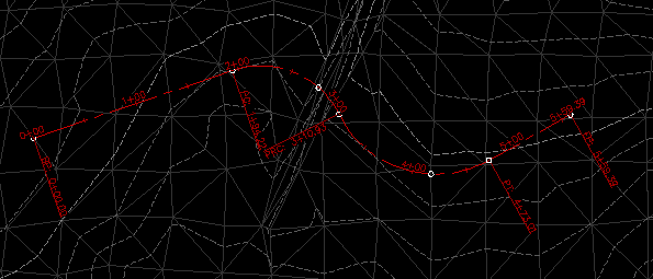
We can now run the CAPFeature command by right-clicking and selecting "Create Alignment/Profile" from the list. After hitting OK, the program asks us to select a location for the Profile View. After selecting the location, we see an Alignment like the one shown below. Notice that all the grade breaks in the source Feature Line were ignored when creating the horizontal alignment geometry.
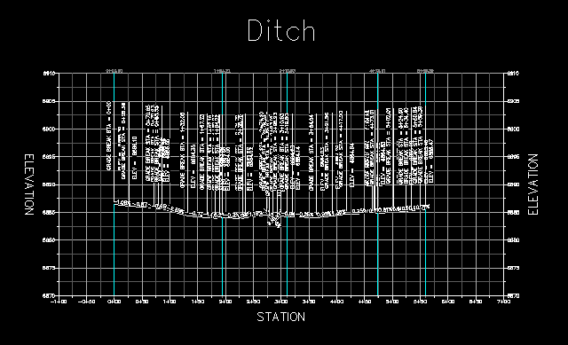
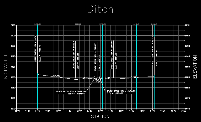
At the same time, a Profile is created from the Feature Line. In the settings for the CAPFeature command, we had deselected the "Prune excess PVIs from Profile" option, so we end up with one PVI for every grade break in the source Feature Line. Since the source Feature Line was created by sampling a surface, there are a lot of PVIs in the Profile, as shown below:
If we run the previous command in exactly the same way, except specify a value of 0.5' for "Prune excess PVIs from Profile", then the CAPFeature command will remove as many PVIs as possible, but still keep the Profile within �0.5' of the source Feature Line at all places along the Profile.
See Also
Creates an alignment and profile from an existing polyline and an existing surface. The surface is sampled at the specified interval, and/or at enough intervals to keep the error within a specified tolerance.
Add a lowering to an existing finish ground profile. Particularly useful for waterlines.
Creates alignments from polylines. Arcs in the polyline are converted to Free Curves, if possible.
Display Points by Station and Offset, as measured along an Alignment. Results are displayed on screen and may also be written to a file.
Prune PVIs from a Finished Ground profile.
Convert an Existing Ground profile (sampled from a surface) to a Finish Grade profile (with editable geometry points).
