SincpacC3D
General Information
Command Summary

CAPSurface
|
SincpacC3D
General Information
Command Summary
CAPSurface |
Description
The CAPSurface command creates an Alignment and Profile from an existing polyline and surface, sampling the surface only at specific intervals and/or at enough points to keep the Profile within a specified range of the surface.
Usage
Type CAPSurface at the command line, and pick the polyline. You may also select a polyline, right-click, and select "Create Align/Prof Sample Surface" from the shortcut menu. You should then see a dialog box like the one shown below:
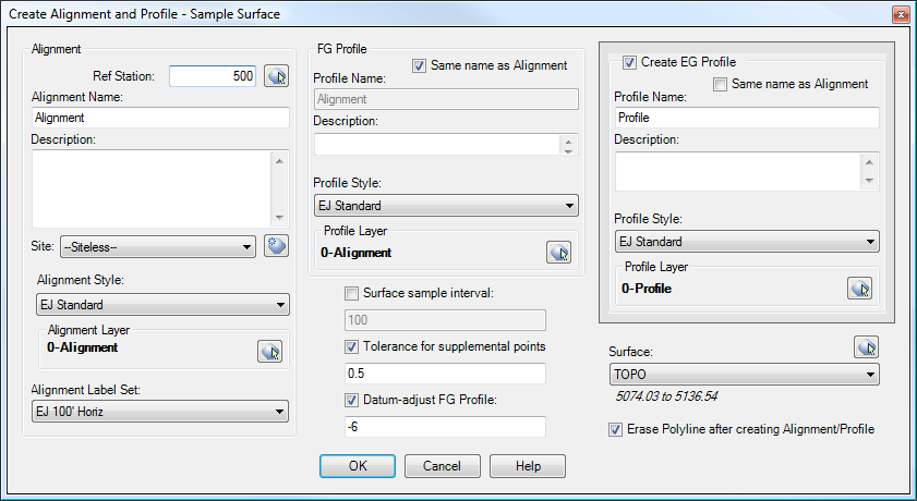
Along the left side of the dialog box are settings for the Alignment.
In the center of the dialog box are options for the new FG Profile created by this command. There are also settings for the Sample Interval and Tolerance for Supplemental Points, as well as an option for datum-adjusting the FG Profile after it is created.
The right side of the dialog box contains an option for creating an EG Profile along the alignment along with the FG Profile. There is also a combo box for selecting the surface to sample, as well as a checkbox for erasing the source polyline after creating the alignment and profile.
Once you have all settings the way you want them, hit OK. You will then be prompted to select a location for a Profile View. If you select a location, then you will see the Create Profile View dialog box. Or, you may right-click or hit the ESC key to skip the Profile View generation. Unfortunately, it is difficult to have any control over the labels that appear on the Profiles in Profile Views. See the notes about the issues with Profile Labels in Profile Views for details.
Surface sample interval:
If this option is checked, then the surface is sampled at the specified intervals. The intervals are measured from station 0+00, so a value of 50 will cause the surface to be sampled at even 50-foot stations. For example, if the Profile starts at station 1+22 and the interval is 50, the first sample station after the start of the alignment will be at 1+50, not at 1+77.
Tolerance for supplemental points:
If this option is checked, as many vertical PVIs as possible are pruned from the final Profile, while still keeping the resulting Profile within the specified tolerance of the source Surface at all points. This option will not prune PVIs added by the "Surface sample interval" command.
Datum-adjust Profile:
If this option is checked, the Profile is datum-adjusted by the specified amount after it is created.
Examples
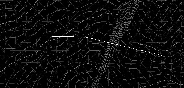
The following examples are all based on creating Alignments and Profiles from the white polyline and the surface shown in the following image. Note the ravine running down the middle; we'll see it in the Profiles.
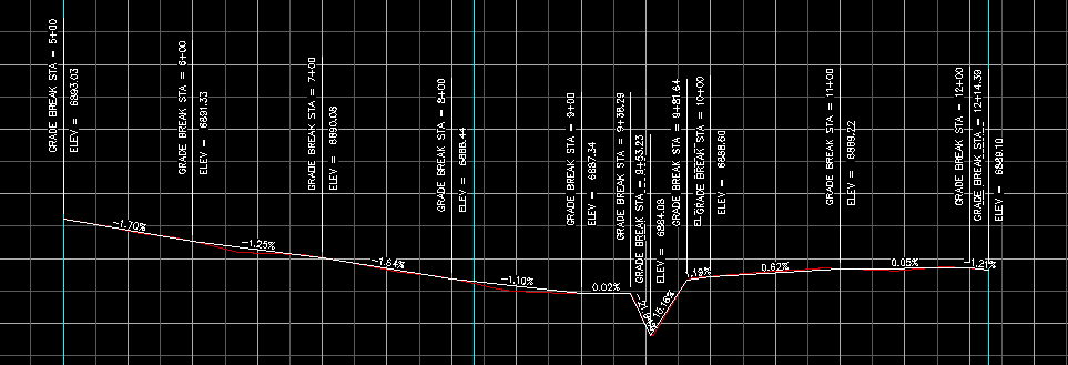
Example 1:
This Profile was created using a "Surface sample interval" of 50 feet. Notice that there is a PVI every 50 feet, regardless of the terrain. (The existing ground can be seen in red.)
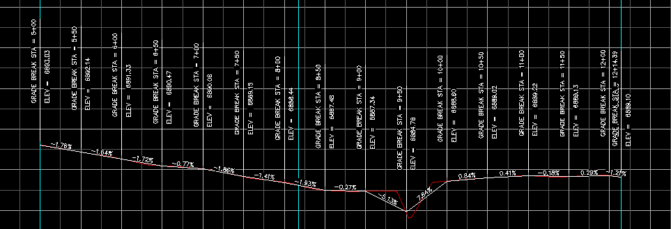
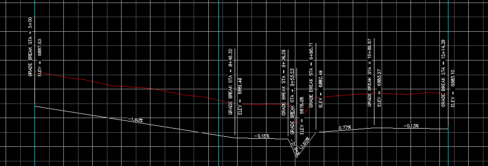
Example 2:
This Profile was created using a "Tolerance for supplemental points" of 1 foot. Notice that this time, the Profile basically follows the existing ground, staying within 1 foot of the EG surface at all points. This results in far fewer PVIs in the Profile.
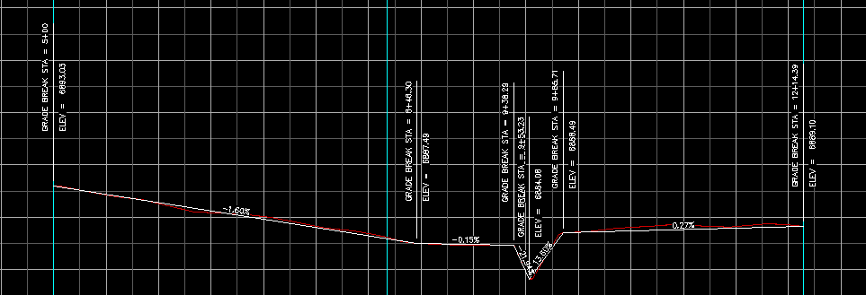
Example 3:
This Profile was created using a "Surface sample interval" of 100 feet, and a "Tolerance for supplemental points" of 0.5 feet. To create this Profile, PVIs are added at all the even 100-foot stations. Then the Profile is compared to the surface, and PVIs are added to the Profile until it is within 0.5 feet of the surface at all points.
Example 4:
This Profile was created using a "Tolerance for supplemental points" of 0.5 feet, and a "Datum Adjustment" value of -6 feet. To create this Profile, PVIs are added to the Profile until it is within 0.5 feet of the surface at all points. The Profile is then datum-adjusted downward by 6 feet. (Again, the red line is the EG Profile created from the surface.)
See Also
Creates alignments and profiles from a variety of objects, including polylines, 3D-Polylines, Feature Lines, and Survey Figures. Various pruning options may be used when creating the alignment and profile.
Add a lowering to an existing finish ground profile. Particularly useful for waterlines.
Creates alignments from polylines. Arcs in the polyline are converted to Free Curves, if possible.
Create a profile from a polyline in a profile view.
Prune PVIs from a Finished Ground profile.
Convert an Existing Ground profile (sampled from a surface) to a Finish Grade profile (with editable geometry points).
