SincpacC3D
General Information
Command Summary

DLPoints
|
SincpacC3D
General Information
Command Summary
DLPoints |
Description
The DLPoints command manages dynamic links between Cogo Points and other Civil-3D entities. This allows the elevations of Cogo Points to change dynamically whenever the "master" object changes. Similarly, the description may be set to display the Station/Offset of the point, and the Station/Offset will also dynamically respond to changes in the model. The "master" object may be a Surface, a Profile, an Alignment, or a linear entity such as a Featureline, Survey Figure, Polyline, or 3D-Polyline.
Note: The EntityTracker may be used to identify Cogo Points that have Dynamic Links.
Usage
Type DLPoints at the command line, or select one or more Cogo Points on-screen, then right-click and select "Dynamic Links" from the shortcut menu. You will then be prompted to select a "master" object for the Cogo Point(s), which can be a Profile, an Alignment, a Surface, or a linear entity such as a Featureline, Survey Figure, Polyline, 3D-Polyline, or Line.
You will then see a dialog box like that below:
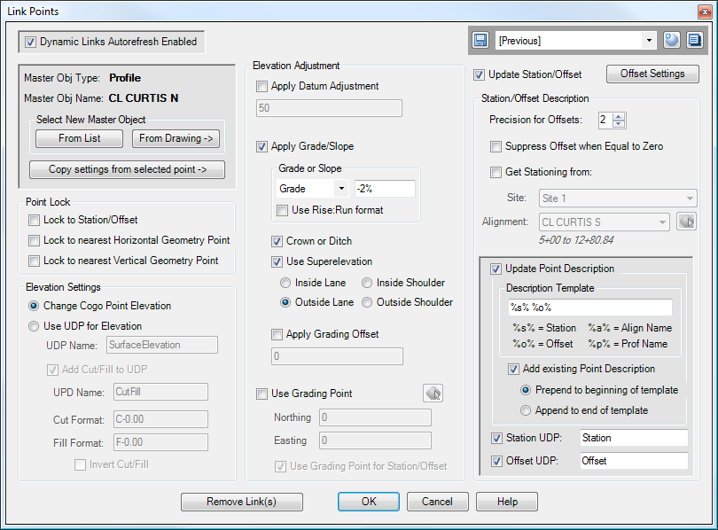
The panel in the upper-left displays the type of the "master" object, along with its name (if applicable). (Note that at this time, the new feature in Civil-3D 2009 for named Featurelines is not supported, so Featureline names will not appear in this panel.)
You may change the "master" object by clicking on one of the buttons in the "Select New Master Object" section, or you may copy all settings from a selected point.
The DLPoints command may also be used to edit the existing links of Cogo Points. Simply select any Cogo Point that has a Dynamic Link, then right-click and select "Dynamic Links".
The checkbox in the upper-left may be used to enable or disable the automatic updating of dynamic links for the current drawing. Typically, this option is left enabled. However, it may also be disabled, in which case the dynamic links may be updated using the DLRefresh command.
Various options in the Dynamic Links may be configured to place values in User Defined Properties (UDPs) on Cogo Points. These UDPs must be correctly configured, and the Point Group Classification must be set, or no data will appear in the UDPs.
Point Lock
These options allow the horizontal location of Cogo Points to be locked to the "master" object.
Note that if you enable this option for a Cogo Point and then attempt to drag it to a new location, the Cogo Point will not move. If you wish to move the point to a new location, either turn off the Point Lock option, or use the MovePoints command, which will move the Cogo Point without altering the dynamic link properties.
Elevation Settings
(Note: these settings are not available in the 2008 version.)
The Elevation Settings are available whenever the "master" object is any type of entity except an Alignment. If the radio button for "Change Cogo Point Elevation" is selected, then the Cogo Point elevation is set from the "master" object. Otherwise, the elevation from the "master" object is placed in the specified User Defined Property (UDP). Note that this UDP is created via normal Civil 3D procedures, by adding new custom properties to a User Defined Classification on the Settings tab. When creating this UDP, select "Elevation" in the "Property field type" selection box in the UDP properties.
Add Cut/Fill to UDP
If the elevation from the "master" object is placed into a UDP, it is also possible to generate a Cut or Fill between the UDP elevation and the Cogo Point elevation. To do this, select the option to "Add Cut/Fill to UDP", and specify the UDP to use for the Cut/Fill. If your Cut/Fill contains any non-digit characters, the Cut/Fill should be a String property. In other words, when creating this UDP, select "String" in the "Property field type" selection box in the UDP properties. If you have your Cut/Fill configured to contain only numeric digits, then you can use another appropriate type, such as "Double".
The Cut Format and Fill Format specify the format to use for cuts and fills. Zeros are used as place holders, and indicate the number of digits to display in the Cut/Fill. Note that you may also pad the beginning of the Cut/Fill with zeros. Characters other than zeros are passed through unchanged. For example, the table below illustrates several example formats. The first column indicates the contents of the "Cut Format" string in the Dynamic Link settings; the result shows the contents that end up in the UDP:
Format String |
Result |
C-0.00 |
C-4.58 |
C-0.0' |
C-4.6' |
C-00.000m |
C-04.583m |
C/F = C-00.00' |
C/F = C-04.58' |
Invert Cut/Fill
Normally, the Cut/Fill value is calculated from the Cogo Point elevation, to the UDP elevation. When this item is selected, the Cut/Fill is reversed, and is calculated from the UDP elevation, to the Cogo Point elevation.
Elevation Adjustment
The various options in this segment are used to adjust the elevation of the Cogo Point. If the "master" object is an Alignment, this section is disabled. Otherwise, various options in this section are enabled or disabled, depending on the type of "master" object.
The following table contains an overview of these options:
Apply Datum Adjustment |
When selected, the specified datum adjustment is applied to the elevation. For example, assume the "master" object is a Surface, and the elevation of the Surface at the Cogo Point is 152.56. If a value of 2.00 feet is specified for the Datum Adjustment, the elevation assigned to the Cogo Point will be 154.56. |
Apply Grade/Slope |
When selected, the elevation of the Cogo Point is adjusted by the specified Grade or Slope. The elevation of the Cogo Point is determined by finding the closest point to the Profile or linear object. This elevation is then adjusted by multiplying the grade or slope by the distance between the Cogo Point and the linear object. If specified, the Datum Adjustment is also applied. |
Grade or Slope |
This field specifies the grade/slope to use for the datum adjustment. You may specify the grade/slope in one of three formats: a percentage grade, a slope in run:rise format, or a slope in rise:run format. The slope specified here is from left to right. In other words, a slope of -2% would start from a high point on the far left to a low point on the far right. |
Crown or Ditch |
The slope is typically specified from left to right. However, when this option is selected, the slope is specified outward in both directions from centerline. So when this option is selected and a grade of -2% is specified, the centerline of the Alignment is the high point, and the grade slopes downward at a 2% in both directions from centerline. |
Use Superelevation |
When specified, the Superelevation settings for the Alignment (in the Alignment Properties, Superelevation tab) are used for the slope. If the Alignment contains any regions where no Superelevation data is defined, then the "Grade or Slope" and "Crown or Ditch" settings are used as default values. |
Apply Grading Offset |
This allow you to lengthen or shorten the offset distance used to calculate the elevation for the Cogo Point. It works the same way as the Grading Settings panel for the SGRD, SGObject, Pt2Feature, and Pt2Profile commands. The specified value is subtracted from the offset distance used to calculate the elevation adjustment. |
Use Grading Point |
When selected, the specified Northing/Easting are used instead of the Cogo Point's Northing/Easting. The primary purpose for this feature is to enable NxN offsets for Feature Lines. Typically, the grade is calculated by finding the closest point on the Feature Line to the Cogo Point. However, for an NxN offset to an angle point, this returns an incorrect result. This feature allows a dynamic link to be created for an NxN offset, and the point can be linked directly to the angle point. However, it can also be used in other situation. For example, it may be used to create an offset to a point on a Surface. With this option enabled, the Cogo Point will get the elevation of the surface at the Grading Point. With this option enabled, the Station/Offset in the Description will be of the Grading Point, and not of the Cogo Point. |
Use Grading Point for Description |
This option is only enabled when both the "Use Grading Point" and the "Update Description" options are enabled. When selected, the Station and Offset come from the location of the Grading Point. Otherwise, the Station and Offset come from the location of the Cogo Point. |
Update Station/Offset
When this option is selected, the Raw Description of the point is dynamically updated with the Station/Offset for the Point. You may also configure the link to update some User Defined Properties (UDPs) in addition to, or instead of, the Raw Description. When the "master" object is an Alignment, the Station/Offset automatically comes from this Alignment, and most other options are disabled (because an Alignment has no vertical data). Note: UDP functionality is not available in Civil 3D 2008.
However, when the "master" object is a different type of object, you may also select a different Alignment as the source for the Station/Offset. This lets you configure a Cogo Point so that its elevation comes from a Surface, but the Station/Offset comes from an Alignment. Or, you can configure the Cogo Point to get its elevation from a ditch Profile, but get its Station/Offset from the road centerline alignment.
The formatting for the Offset may be altered by clicking the "Offset Settings" button.
Get Stationing from: |
Specify an alternate alignment for the stationing. This option is not available if the master object is an Alignment. |
Precision for Offsets |
Number of decimal places for the Offset. (The Station format comes from the Alignment Feature Settings.) |
Suppress Offset when Equal to Zero |
When selected, this option causes the Offset to be omitted from the description when it is equal to 0. |
Update Point Description |
When selected, this option causes the Raw Description of the point to be modified as specified by the Description Template. |
Description Template |
The Description Template is used to create the Raw Description for the point. The string "%s%" in this Template gets replaced by the current Station string for the point; the string "%o%" gets replaced with the Offset; the string "%a%" gets replaced with the Alignment name, and the string "%p%" gets replaced with the Profile name. All other characters in the Template are passed through unchanged. |
Add existing Point Description |
This option is only available when a Point Link is first created. When selected, the current Raw Description for the point is added to the Description Template. As an example, this feature is useful for points that have been created using the "Create COGO Points from Corridor" feature. These points already have a description (such as "ETW", "Hinge", etc.), taken from the Point Codes for the subassemblies used in the Corridor. With this option, a dynamic Station/Offset can be added to these points, without losing the description they already have. |
Station UDP |
When selected, this option causes the Station to be placed in the specified UDP. A UDP must be defined, and applied to the point via a Point Group, in order for this option to work. The UDP should be either a String or a Station property. In other words, when creating this UDP, select either "String" or "Station" in the "Property field type" selection box in the UDP properties. |
Offset UDP |
When selected, this option causes the Offset to be placed in the specified UDP, formatted according to the Offset Settings. If your Offset contains any non-digit characters, the Offset should be a String property. In other words, when creating this UDP, select "String" in the "Property field type" selection box in the UDP properties. If you have your Offset configured to contain only numeric digits, then you can use another appropriate type, such as "Double". | Alignment UDP | When selected, this option causes the Alignment Name to be placed in the specified UDP. The Alignment UDP should be a String property. |
Selecting Multiple Points
When you run the DLPoints command and multiple Cogo Points are selected, all Cogo Points are modified to use the same values, except for the Grading Point. The Grading Point can only be changed for each Cogo Point individually. When you select multiple Cogo Points, the "Use Grading Point" option is disabled.
The initial values of the dialog box are taken from the first point you select while selecting the Cogo Points.
UDP Settings
(Note: these settings are not available in the 2008 version.)
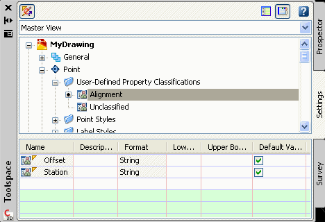
The following images illustrate settings for UDPs, should you wish to use them. This first image shows the UDP definitions. In this example, the UDPs are created in a classification named "Alignment". Note that both UDPs are String values. The names of the UDPs should match the names used in the DLPoints dialog box, while creating the Dynamic Point Link.
This image shows the Points in the drawing. Notice that the points have been added to a Point Group that uses our new "Alignment" UDP Classification. The "Station" and "Offset" UDPs now appear in the list.
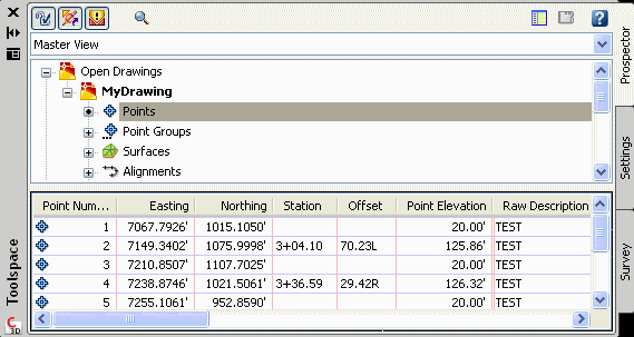
In the above image, Points 2 and 4 have been configured with Dynamic Links that use the "Station" and "Offset" UDPs. These points now have dynamic Station and Offset, located in their own columns, and the values will change if the points are moved, or if the Alignment is moved, or if Station Equations are applied to the Alignment, etc.
Examples
Consider the image below (click on the image for a larger view):
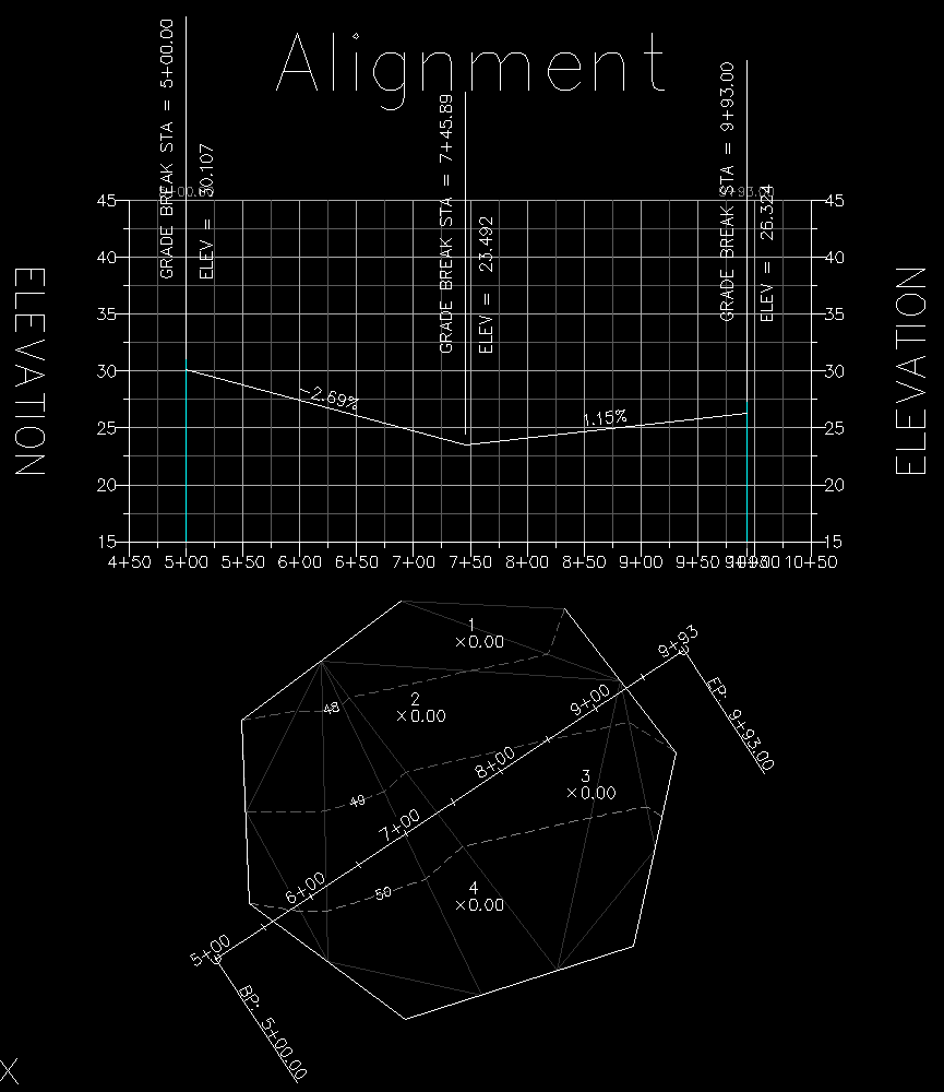
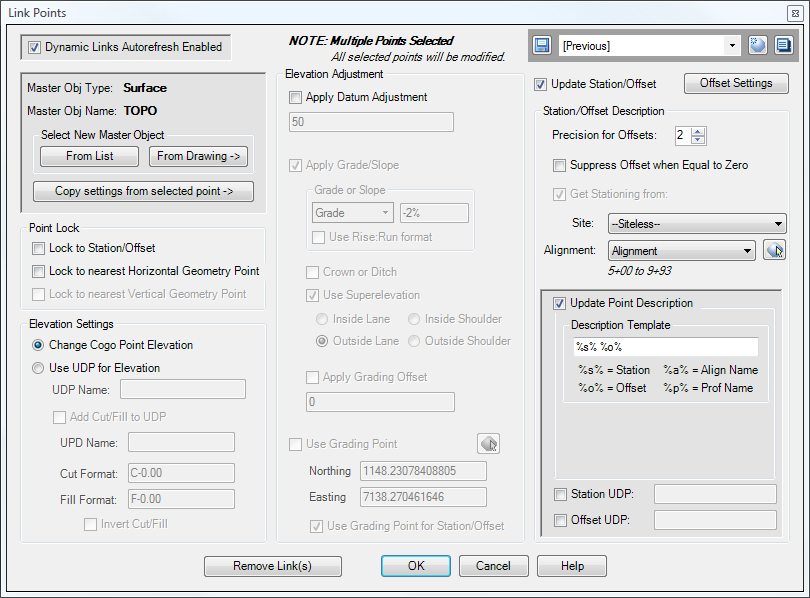
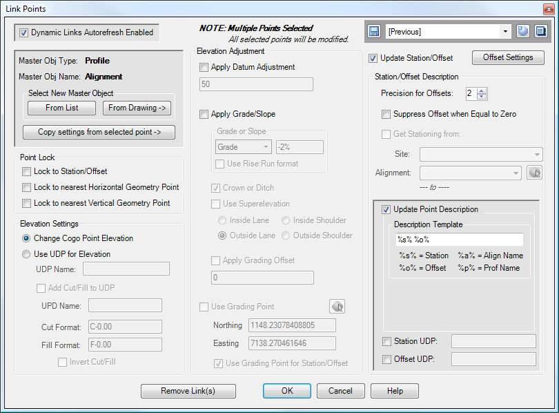
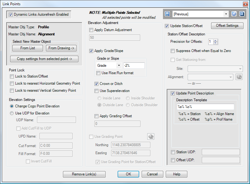
Let's now link Points 1 and 3 to the Surface, and Points 2 and 4 to the Profile. In addition, we'll also configure Points 1 and 3 to get their Station/Offset from the Alignment. The settings are as-shown in the following two dialog boxes:
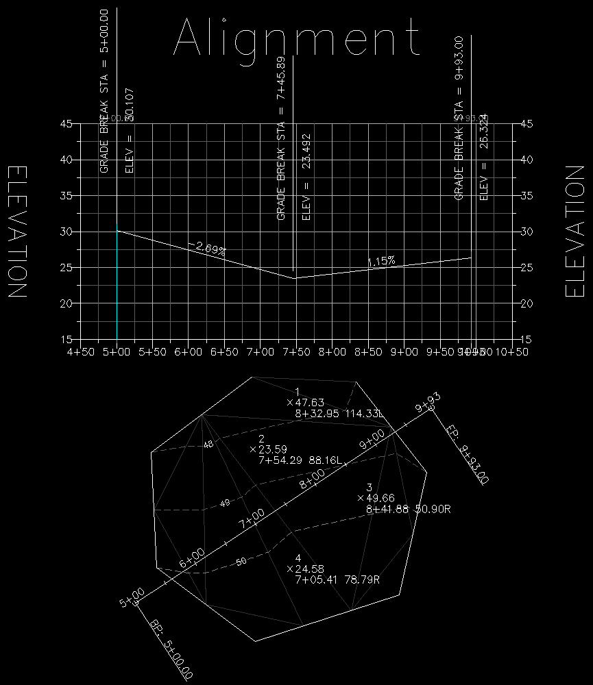
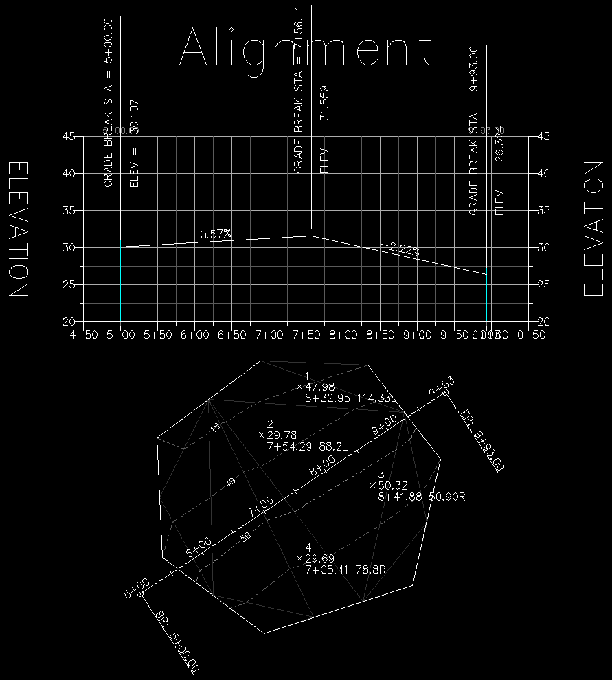
And here is the result:
The following image shows what happens when we edit the Surface and the Profile. Notice that the elevations of the Cogo Points have automatically updated to reflect the new geometry.
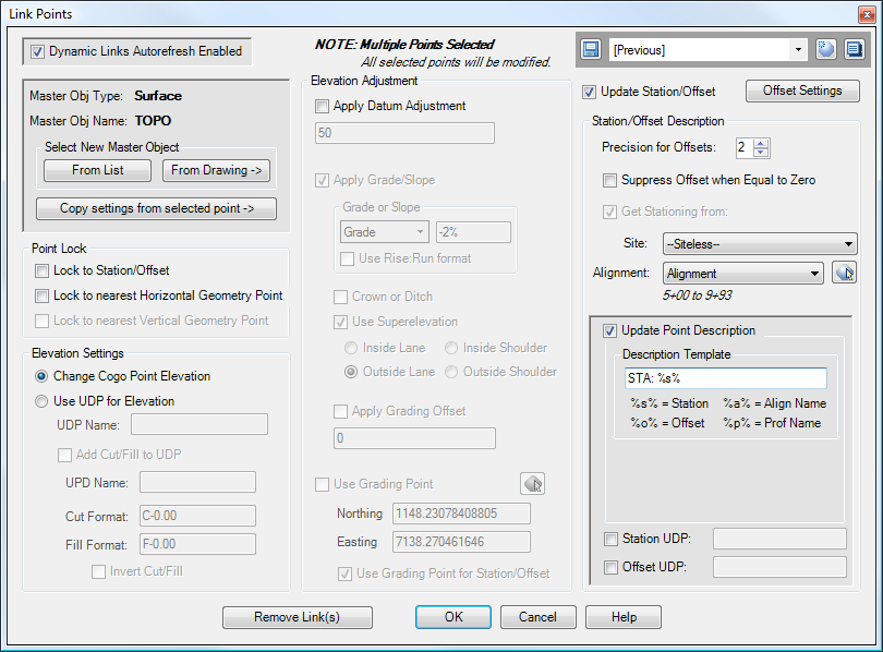
And now, let's select Points 2 and 4 again, then edit their links so that they look like this instead:
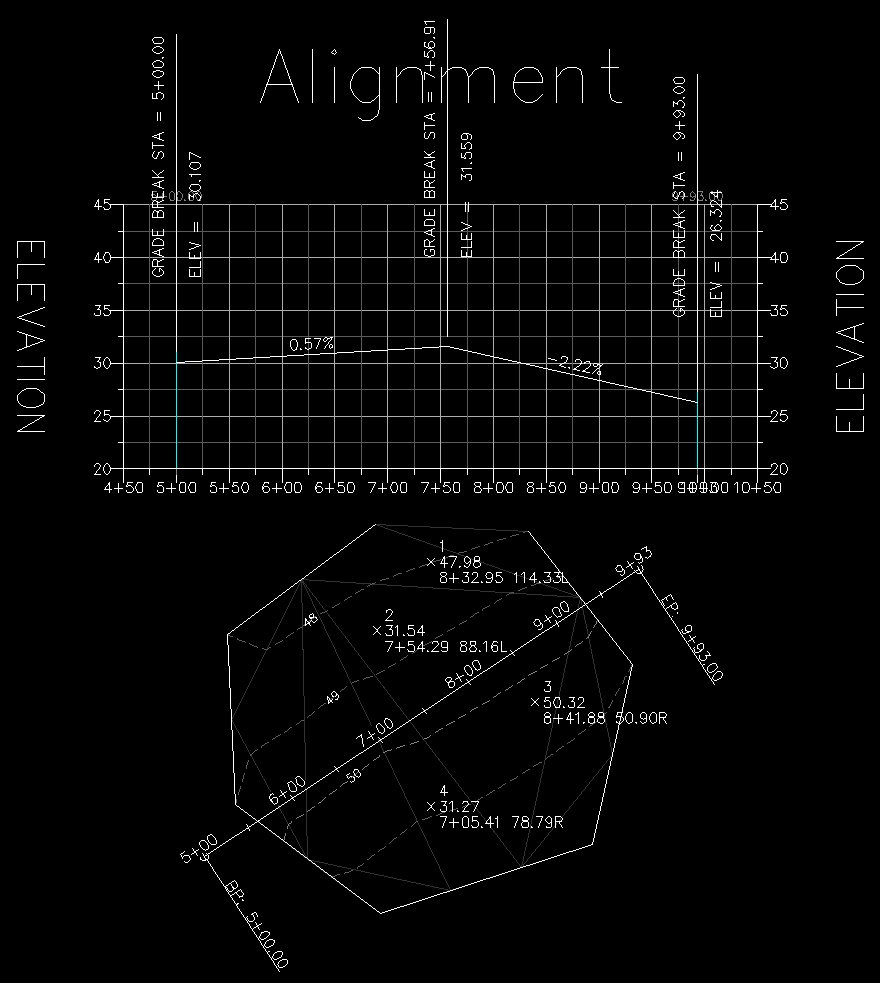
The new result is shown below. Note that the grades have changed now, and are down 2% from centerline. In addition, we changed the "Precision for Offsets" to 1, so the offset distance is rounded to 1 decimal place. We did not change the links for Points 1 and 3, so they still have their offset distances rounded to 2 decimal places.
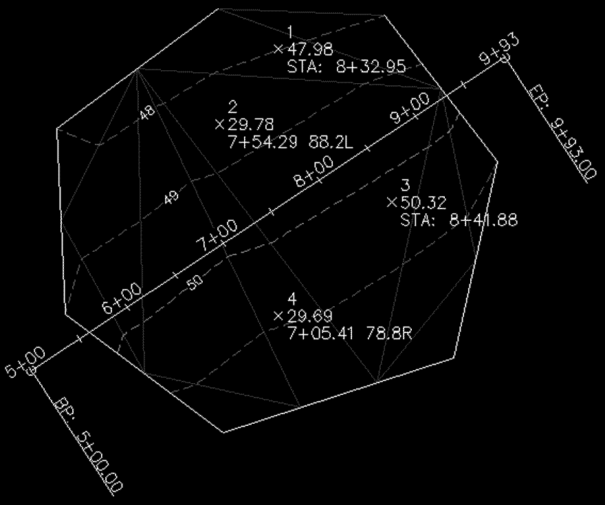
For this final example, let's select Points 1 and 3 again, then edit the Description Template in the links to look like this:
The new result is shown below:
See Also
Displays geometry and interval points along an alignment and profile, and can print the output to delimited output files (CSV, tab-delimited, etc.) or directly to a printer. May also be used to generate Cogo Points along Alignments, or display a Surface elevation at each station, along with a Cut/Fill between the Surface and Profile at each Station.
A Cogo Point browser, editor, and reporting tool, all rolled into one. Displays selected points in a grid, including Station and Offset, with options for editing points, adding/removing them from Point Groups, and printing them to delimited output files (CSV, tab-delimited, etc.) or directly to a printer. Also includes the ability to display a Surface elevation at each point, as well as a Cut/Fill between the Cogo Points and Profile/Surface.
Creates linked PVIs from one Profile to one or two other Profiles; particularly useful for creating linked center, left, and right profiles for Three-Line Profiles.
Allows User Defined Properties on Cogo Points to be automatically populated with coordinates in alternate Coordinate Systems.
Enables or disables the automatic updating of Dynamic Links for a drawing.
Manages dynamic links between Profile PVIs and other Civil-3D entities. This allows the elevations of PVIs to change dynamically whenever the "master" object changes. The "master" object may be a Surface, another Profile, or an adjacent PVI on the same Profile.
Refreshes all Dynamic Links in the drawing that are known to be out-of-date.
Refreshes all Dynamic Links in the drawing.
Refreshes all Dynamic Links attached to selected objects.
Displays information about items underneath the cursor.
Move points in the drawing. Points are only moved horizontally, with no datum adjustment, and may be selected by Point Group.
