SincpacC3D
General Information
Command Summary

DLProfiles
|
SincpacC3D
General Information
Command Summary
DLProfiles |
Description
The DLProfiles command manages dynamic links between Profile PVIs and other Civil-3D entities. This allows the elevations of PVIs to change dynamically whenever the "master" object changes. The "master" object may be a Surface, another Profile, or an adjacent PVI on the same Profile.
Usage
Type DLProfiles at the command line, or select a Profile on-screen, then right-click and select "Dynamic Links" from the shortcut menu. You will then see a dialog box like that below:
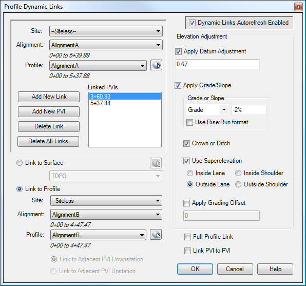
In the top left, you may select a different Profile. Any links that exist on the selected Profile will appear in the list box. You may add or remove links from this list by clicking on the appropriate buttons. The checkbox in the upper-right may be used to enable or disable the automatic updating of dynamic links for the current drawing. Typically, this option is left enabled. However, it may also be disabled, in which case the dynamic links may be updated using the DLRefresh command. The rest of the dialog box displays the settings for the currently-selected PVI link.
Important: Dynamic Links will only work for PVIs that are on the Alignment, i.e. between the Starting Station and Ending Station of the Alignment. Civil-3D will allow you to add PVIs to Profiles at stations that are not on the Alignment, i.e. before the Starting Station or after the Ending Station of the Alignment. However, if a PVI is at a station that is not on the Alignment, there is no way to determine a Northing/Easting coordinate for the PVI. Since the Northing/Easting of the PVI is needed to calculate the new elevation for the PVI, Dynamic Links will not work on PVIs that are beyond the ends of the Alignment.
In the lower-left corner of the dialog box, you may select the "master item" for the PVI. The list of available "master" Profiles will not contain Profiles that would create a "circular reference"; in other words, once you link a PVI in Profile A to Profile B, you cannot link a PVI in Profile B to Profile A.
Adjacent PVI Links
When the "master" Profile is the same as the source Profile, the options for "Link to Adjacent PVI" will become active. A Dynamic Link may only be created to one of the adjacent PVIs. This option is useful for maintaining a set grade through a segment of the Profile.
Elevation Adjustment
To determine the new elevation for the PVI, an elevation is first retrieved from the "master" object. If the PVI is linked to a Surface, the Northing/Easting of the PVI is used to get an elevation from the Surface.
If the PVI is linked to another Profile, the Northing/Easting of the PVI is used to get the station/offset of the PVI, as determined from the "master" Profile. That station is then used to get an elevation from the "master" Profile, and the offset is used for applying a Grade/Slope adjustment (if enabled). When the "Use Superelevation" option is selected, the superelevation parameters of the "master" Profile's Alignment are used for the slope. For areas where no superelevation parameters are defined, the specified Grade/Slope and Crown values are used.
Full Profile Link
When this option is activated, all PVIs in the Profile are adjusted by the same amount. The entire Profile moves up and down with the linked PVI. When this option is enabled, the "Add New Link" button is disabled, because all PVIs are being controlled by the one link. Note that if you already have multiple PVI links on this Profile and you activate this option, you will be warned that all other PVI links on this Profile will be deleted. This option is disabled when "Link PVI to PVI" is selected.
Link PVI to PVI
When this option is activated, the PVI in this Profile will adjust both horizontally and vertically to match the closest PVI in the "master" Profile. For this type of link, the new elevation is based on the PVI elevation on the "master" Profile, and not the Profile elevation. Its primary purpose is to link left and right Profiles to a centerline Profile, so that the left and right Profiles automatically change with the centerline Profile.
Examples
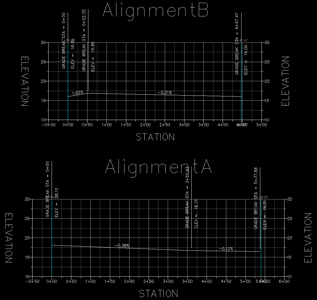
The following examples use this layout, consisting of two Alignments with Profiles. Click on the image to see a larger view.
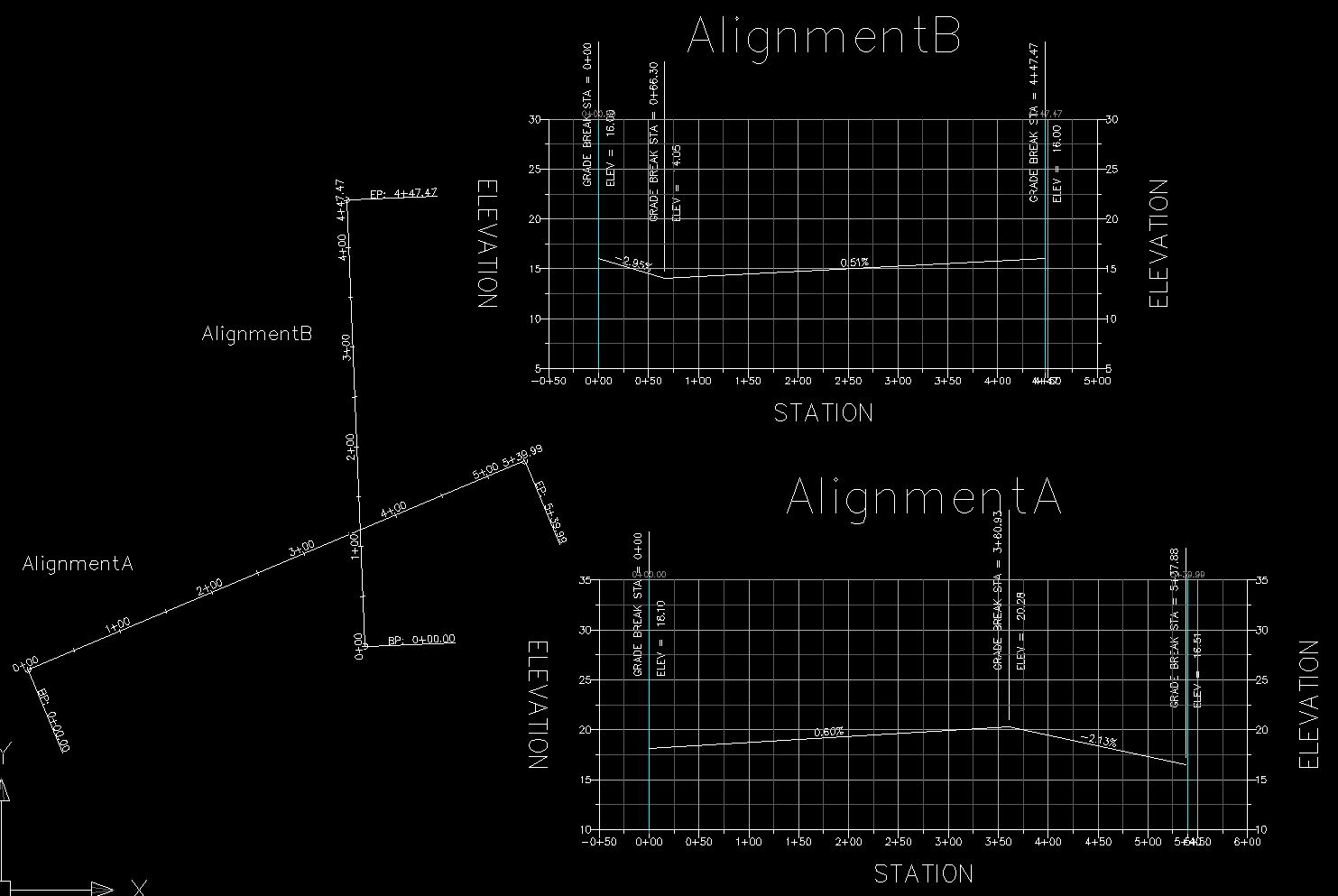
Example 1:
Note that AlignmentA has a PVI at station 3+60.93, where it intersects Alignment B. Assume we wish to link this PVI to the Profile on AlignmentB, so that anytime we move the profile on AlignmentB, the profile on AlignmentA will adjust to match.
To accomplish this, click on the "Add New Link" button, and then click near the PVI in the drawing. Note that you may pick in either Plan View or in the Profile View. Tracking lines will follow the cursor, and point to the two PVIs closest to the cursor in each direction. Simply click when the cursor is closest to the PVI that you wish to select. This will create a new link for that PVI.
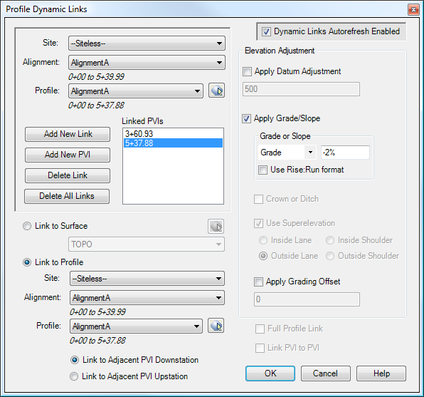
We now need to link this PVI to the profile in AlignmentB, as seen in the dialog box below:
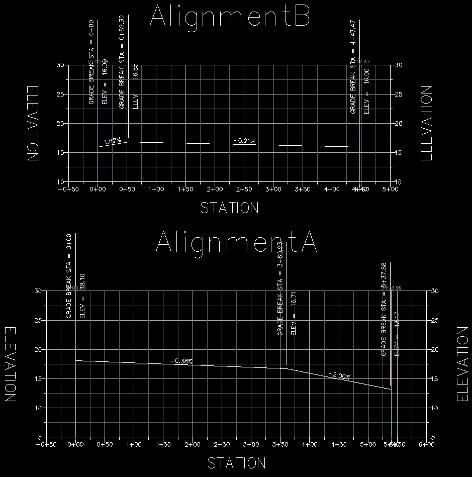
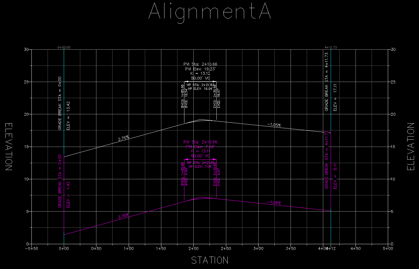
As soon as we click OK in the dialog box, the profile attached to AlignmentA will update itself, and the PVI elevation will match the elevation of AlignmentB, as shown in this image:
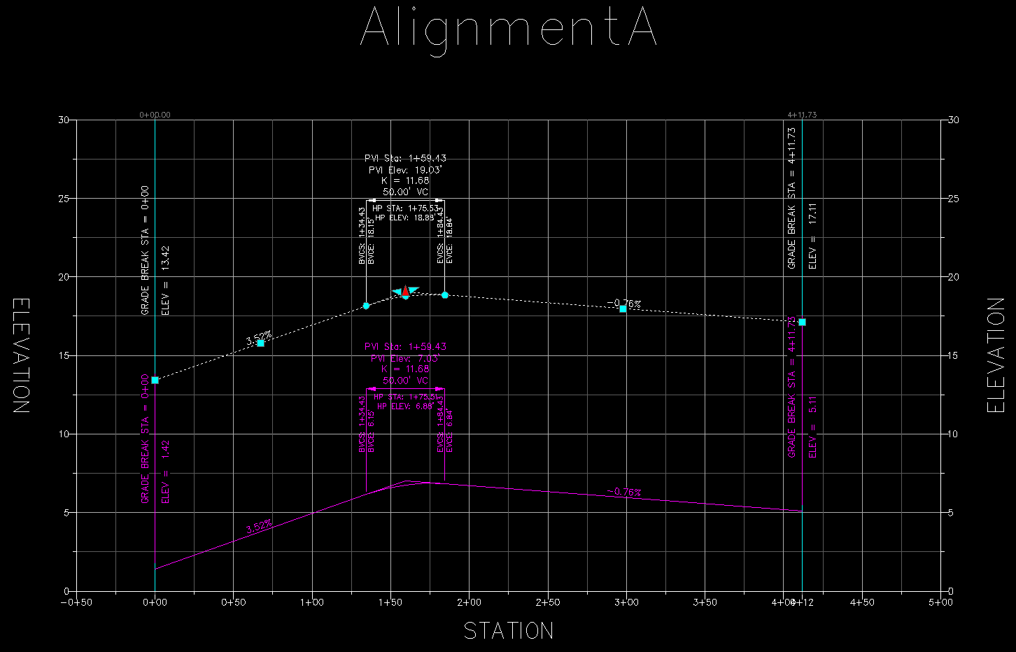
If we then drag a PVI in AlignmentB to a different location, the PVI in AlignmentA will automatically change in response, as seen in this image below (click for a larger view):
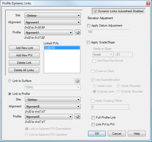
Example 2:
Now let's assume that we want to hold a 2% grade downward from the PVI in our last example, to the PVI at the end of the Profile. So let's add a new PVI link to the PVI at 5+37.88 by clicking the "Add New Link" button. For this PVI, we select "AlignmentA" as the "master", which enables the "Link to Adjacent PVI" radio buttons at the bottom-left. We wish to link the PVI at station 5+37.88 to the PVI just before it, so in this case, we select "Link to Adjacent PVI Downstation". We also select the "Apply Grade/Slope" button, and key in a grade of -2%, as seen in the dialog box below:
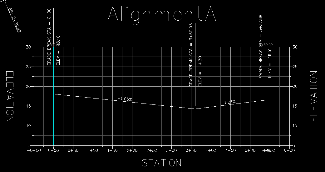
When we click OK in the above dialog box, the profile for AlignmentA will adjust as seen below:

And now, if we drag a PVI in AlignmentB, then AlignmentA will automatically adjust as seen below. Note that the PVI at 3+60.93 in AlignmentA has adjusted to the new elevation of AlignmentB, and the PVI at 5+37.88 has also adjusted to maintain the 2% grade downward from the adjacent PVI.
Example 3:
In the following example, the white profile is the centerline, and the magenta profile is the right side. (Click on the image to see a larger version.)
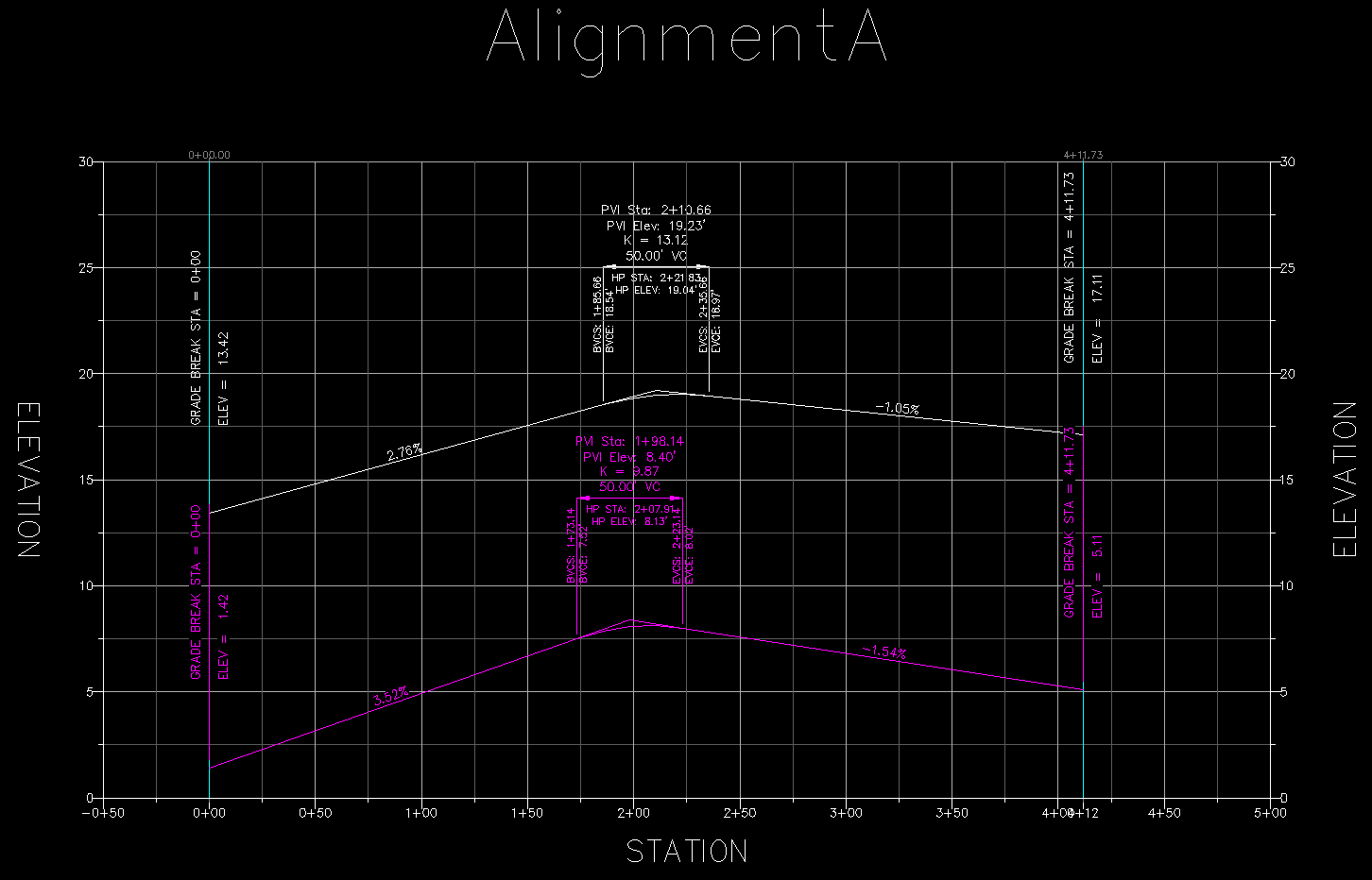
Now let's link the vertical curve on the right side to the one on the centerline. We'll add a PVI Link to the PVI at station 1+98.14 of the right-side alignment, as shown below:

To make things easy to see in the image, let's key in an elevation difference of -12 feet. When we hit OK, the right-side Profile will automatically adjust to match the centerline, as seen below:
Now let's grab the PVI at Station 2+10.66 on the centerline (white) Profile, and drag it to a new location. Note that the right side (magenta) Profile moves along with it.
See Also
Displays geometry and interval points along an alignment and profile, and can print the output to delimited output files (CSV, tab-delimited, etc.) or directly to a printer. May also be used to generate Cogo Points along Alignments, or display a Surface elevation at each station, along with a Cut/Fill between the Surface and Profile at each Station.
A Cogo Point browser, editor, and reporting tool, all rolled into one. Displays selected points in a grid, including Station and Offset, with options for editing points, adding/removing them from Point Groups, and printing them to delimited output files (CSV, tab-delimited, etc.) or directly to a printer. Also includes the ability to display a Surface elevation at each point, as well as a Cut/Fill between the Cogo Points and Profile/Surface.
Creates linked PVIs from one Profile to one or two other Profiles; particularly useful for creating linked center, left, and right profiles for Three-Line Profiles.
Allows User Defined Properties on Cogo Points to be automatically populated with coordinates in alternate Coordinate Systems.
Enables or disables the automatic updating of Dynamic Links for a drawing.
Manages dynamic links between Cogo Points and other Civil-3D entities. This allows the elevations of Cogo Points to change dynamically whenever the "master" object changes. Similarly, the description may be set to display the Station/Offset of the point, and the Station/Offset will also dynamically respond to changes in the model. The "master" object may be a Surface, a Profile, an Alignment, or a linear entity such as a Feature Line, Survey Figure, Polyline, or 3D-Polyline.
Refreshes all Dynamic Links in the drawing that are known to be out-of-date.
Refreshes all Dynamic Links in the drawing.
Refreshes all Dynamic Links attached to selected objects.
