SincpacC3D
General Information
Command Summary

StakeFeatures
|
SincpacC3D
General Information
Command Summary
StakeFeatures |
Description
The StakeFeatures command creates elevated offset points along Feature Lines, Survey Figures, Parcels, Polylines, or 3D-Polylines for survey stakeout.
Usage
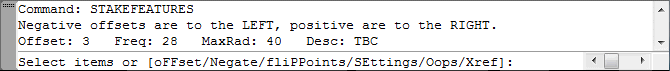
Type StakeFeatures at the command line, and pick the feature lines or other linework. To place offset points along a Parcel, select the Parcel Area label. You may also enter "FF" to change the current offset distance, or "SE" to call up the Settings dialog box. The command line will show you a brief synopsis of the current settings, along with the prompt, as seen below:
Or if you prefer, you may select linework, right-click, and select "Set Offset Points" from the shortcut menu. The dialog box shown below will then appear automatically.
Note that all linear entities in AutoCAD have an inherent "direction". This command is designed to be used primarily with feature lines and polylines, which have a definite "beginning" and "end". The StakeFeatures command will always place points from the start of the object to the end of the object, and the point numbers will increase in that direction. "Left" and "Right" are also specified in relation to the direction of the line. If you wish to set points in the opposite direction, reverse the direction of the feature line or polyline using the Grading -> Edit Feature Lines -> Reverse command in Civil-3D.
The various command line options perform the following tasks:
oFFset |
Changes the Offset Distance via the command line. |
Negate |
Flips the sign of the Offset Distance and the Line Stake Offset Distance from positive to negative, or vice-versa. |
fliPPoints |
Flips the last set of points to the other side of the feature. Basically, this option deletes the last set of points and resets them on the other side. |
SEttings |
Calls up the full Settings dialog, as described below. |
Oops |
Removes the last set of points. Similar to "Undo", except at this time, it will only remove the most-recent set of points. It will not let you undo more than one set of points. However, you may still cancel the StakeFeatures command and use the standard "Undo" command. |
Xref |
Switches to "Nested Selection Mode", allowing linework in XREFs to be selected as the source object. Offset points are created in the current drawing. Right-click or hit ENTER to exit "Nested Selection Mode", and return to the standard prompt. (This option is not available in the Free Edition.) |
Typing "SE" at the command prompt calls up the Settings dialog box shown below:
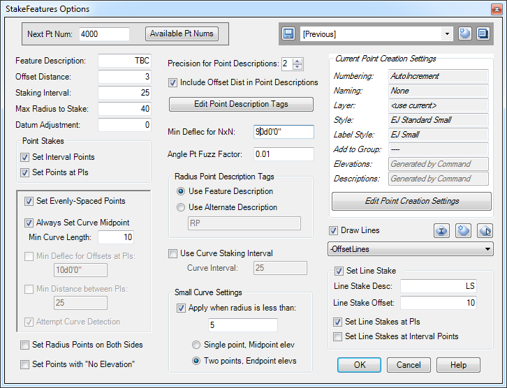
At the upper-left is a place to specify the next point number. You may type a new point number in this box and hit the "Enter" key, and if the point number is currently in-use, it will automatically jump to the next available number. You may also click on the "Available Pt Nums" button to see what point numbers are available for use. In the upper-right corner is the Quickset panel. (Note that some of the options for this command are disabled in the Free Edition.)
Description of the options:
Next Pt Num |
Specifies the next point number to use for generated points. Click on the "Free Pt Nums" button to see a list of available point numbers. |
Feature Description |
String used in the description for points. Depending on the settings for other options on this page, this string may be combined with the offset distance and/or a description tag to form the description for points. |
Offset Distance |
Offset distance for points. Negative numbers are to the left side of the polyline or featureline, positive numbers are to the right side. |
Staking Interval |
Interval between stakes. When "Set Evenly-Spaced Points" is checked, this is the maximum interval between offset points, as measured along the feature line or polyline. |
Max Radius to Stake |
Radius points are set for arc segments if the radius is less than or equal to this value. |
Datum Adjustment |
A vertical datum-adjustment to apply to the elevation for each point as it is calculated. |
Point Stakes |
The "Set Points at PIs" and "Set Interval Points" settings control how points are created. When the "Set Points at PIs" option is selected, points are set at all horizontal and vertical geometry points (angle points, points of curvature, grade breaks, etc.) in the feature line. When "Set Interval Points" is selected, points are set at the Interval points, as controlled by the "Staking Interval". You may select either one or both of the options. Points are assigned descriptions that include the corresponding Description Tag, if the tag is enabled. |
Set Evenly-Spaced Points |
This option is only enabled when "Set Points at PIs" is selected. This option causes intermediate points to be created at evenly-spaced intervals, using the Staking Interval as the maximum distance between points. |
Always Set Curve Midpoint |
This option is only available when "Set Evenly-Spaced Points" is selected. It forces a point to be set at the midpoint of the curve, as long as the curve length is greater than the minimum curve length specified. |
Min Deflec for Offsets at PIs |
This option is only available when "Set Points at PIs" is selected, and "Set Evenly-Spaced Points" is NOT selected. It prevents points from being set at PIs that have deflection angles smaller than the specified value. It is useful for limiting the number of points that are set along Feature Lines, especially daylight lines, which may contain a large number of PIs. This option only affects points set at PIs, and not points set according to the Staking Interval. (See Example 5 below.) |
Min Distance between PIs |
This option is only available when "Set Points at PIs" is selected, and "Set Evenly-Spaced Points" is NOT selected. It prevents points from being set along PIs when they fall within the specified minimum distance of another PIs. It is useful for limiting the number of points that are set along Feature Lines, especially daylight lines, which may contain a large number of PIs. This option only affects points set at PIs, and not points set according to the Staking Interval. (See Example 5 below.) |
Attempt Curve Detection |
This option is only available when either "Min Deflec for Offsets at PIs" or "Min Distance between PIs" is selected. When selected, it causes the StakeFeatures command to analyze the selected linework, and attempt to locate "curves" in the source linework (even if the linework is composed of 3D-Polylines or Feature Lines with intermediate grade points set). If curves are found, the pruning commands are suppressed for those PIs. This forces points to be set at both ends of curves, despite the settings of "Min Deflec for Offsets at PIs" and "Min Distance between PIs". (See Example 5 below.) |
Set Radius Points on Both Sides |
By default, Radius Points are only created on the same side of the feature as the offset stakes; therefore no radius point is set if the offset points are being placed along the outside of a curve. When this item is checked, radius points are created for all arc segments, as long as the curve radius is smaller than the setting for the 'Max Radius to Stake' option. |
Set Points with |
Typically, the elevations for the points comes from the linework. However, if this option is selected, all points are generated with "No Elevation". This is particularly useful when the points should be set along one object, but the elevations should come from another object. After setting the points with "No Elevation", you may then use commands such as Pt2Profile or Pt2Feature or the default Civil-3D "Elevations from Surface" command to set the point elevations. |
Precision for Point Descriptions |
If the Offset Distance is included in the Point Description, this value specifies the desired precision for the distance, i.e. the number of digits to the right of the decimal. Trailing zeros to the right of the decimal point are omitted. |
Include Offset Distance in Point Descriptions |
When selected, the offset distance is prepended to the Feature Description. For example, in the dialog box shown in the image above, Feature Description is set to "EOC" and Offset Distance is set to "3". Therefore, all points will be created with descriptions like "3EOC". If Description Tags are also enabled, the description may also contain a description tag, such as "3EOC PC" for a three-foot offset to a point of curve. |
Edit Point Description Tags |
Click this button to edit additional tags that may be added to the description for all points set near horizontal geometry points. See below. |
Min Deflection for NxN offset |
At an angle point, if the deflection between the course in and the course out of the angle point is greater than this value, only a single NxN offset is created to the point. If the deflection is less than this value, two offsets are set for the point, one for the course in and one for the course out. Set this value to 0 degrees if you always want only a single NxN offset set on the inside of angle points, and set it to 180 degrees if you always want two offsets set on the inside of angle points. The default value is 90 degrees. |
Angle Point Fuzz |
Specifies a "tolerance" value for how close together two offset points should be set on angle points. When the angle point is supposed to get two offset points, one for the course in and one for the course out, but the offsets fall within this tolerance of each other, only a single offset point is set instead of two. (See Example 2 below.) |
Radius Point Description Tags |
When "Use Feature Description" is selected, the description for radius points is generated using the Feature Description specified for the offset points. When "Use Alternate Description" is selected, the specified string is used for the radius points. In both cases, the Radius of the curve is also included in the description. |
Use Curve Staking Interval |
When selected, this option allows a different staking interval to be specified for curves. This is useful for setting points at 50-foot intervals on straight segments and 25-foot intervals around curves, for example. |
Small Curve Settings |
When selected, this option suppresses offset stakes for curves with small radii, and sets only the radius point. This occurs if a curve has a radius less than or equal to the specified value. The radio buttons control how many points are created, and with what elevations. When "Single point, Midpoint elev" is selected, only one Cogo point is created at the radius point, and it will have the elevation of the midpoint of the curve. When "Two points, Endpoint elevs" is selected, two Cogo points are created at the radius point, one with the elevation of the start of the curve, the other with the elevation of the end of the curve. |
Point Creation Settings |
The upper-right portion of the dialog box contains the Point Creation Control, which summarizes the current Point Creation Settings. You may adjust these settings by clicking the "Edit Point Creation Settings" button, which will take you to the Point Creation Dialog. Note that the Elevation and Description settings are not available for this command, since these values are generated for each Cogo Point by the StakeFeatures command itself.. |
Draw Lines |
When selected, a line is drawn between the new Offset Cogo Point and the point it references on the source object. This line is drawn on the specified layer. |
Set Line Stakes |
When selected, an additional line stake is created for each point. This additional line stake is basically a "second offset" for each point. The description and offset for the line stake are specified in the text boxes. When "Set Line Stake at PIs only" is checked, line stakes are only created at featureline PIs. Only the primary offset point is calculated at all other points. Also, Line Stakes can only be set at points that have an Offset Stake, so disabling settings in the "Point Stakes" section will also disable the corresponding option in this section. |
Special tags may be appended to the description of all offset points set at horizontal or vertical geometry points. Clicking on the "Edit Point Description Tags" button will call up the following dialog box, which may be used to edit those description tags:
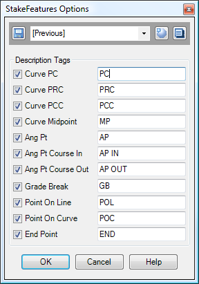
Note that these tags, when enabled, are applied only to offsets near horizontal and vertical geometry points. The description for all interval points will consist of the Feature Description, with no tags.
Examples
Example 1:
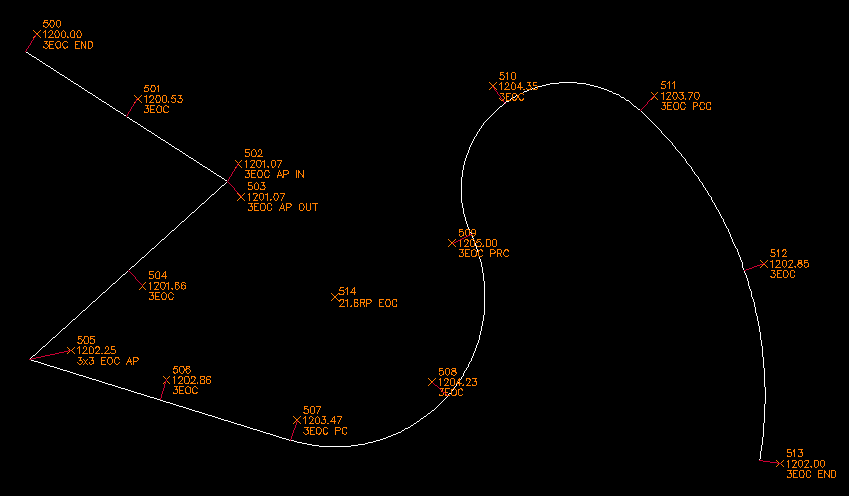
The following image illustrates a feature line labeled with the settings shown in the dialog box in the image above, except the Line Stakes were turned off to set the points in the image below. The offset distance is set to "-3", which creates points three feet to the left side of the linework. Notice that two offsets are set on the outside of angle points, and a single 3x3 offset is generated for the inside of angle points. The option for setting radius points on both sides is disabled, so radius points are only set on the left side. The option for "Set Evenly-Spaced Points" is selected, so points are evenly-spaced along each segment. Also, the option to "Draw Lines" is selected, so the red lines are drawn between the feature point and the offset point.
The image below shows slightly-different settings. The offset is now "3" instead of "-3", so the offset points are on the right side. The option for setting radius points on both sides is selected, so radius points are set on both the left and right sides, as long as the radius is smaller than the maximum distance specified (30 feet). Also, the option for "Set Evenly-Spaced Points" is now turned off, so intermediate points are set every 25 feet, as measured from the start of the polyline.
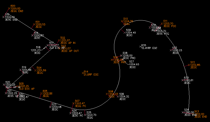
The precision for Point Descriptions is set to "2", so the description for Point 535 is "15.41RP EOC". However, the description for point 514 is "21.6RP EOC", since the radius of that curve is 21.60, and trailing zeros are omitted.
Example 2:
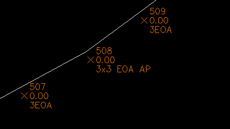
The image below shows what can happen on some angle points.
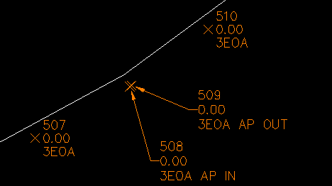
The deflection in the angle is very slight, so Points 508 and 509 end up almost on top of each other. In this particular case, the points happen to be about 0.4' from each other. So if we instead use a value of 0.5' for the Angle Point Fuzz Factor, we end up with these results, with a single 3x3 offset on the outside of the angle point. This angle point is in the same place that the vertex of an offset polyline would be, if we created an offset polyline from the feature we are staking out.
Example 3:
The following diagram illustrates EOA offsets set 3 feet left of the feature, along with Line Stakes set at 10 feet left. The featureline has been offset by 3 feet and 10 feet (the dashed grey lines) for reference, and similar lines have been drawn through the line stakes to the points they reference.
Example 4:
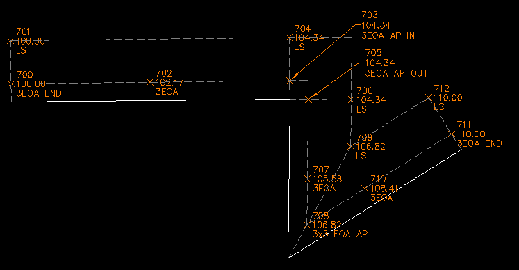
The following image illustrates a current problem with the Line Stakes. Currently, the Line Stakes are calculated basically the same way as the offset stakes. In this case, Point 717 is basically a 10x10 offset to the featureline. This works fine when the segments are lines. However, this does not create a correct line stake when curves are involved. The orange segment in the image below is a straight line that should hit the vertex of the featureline.
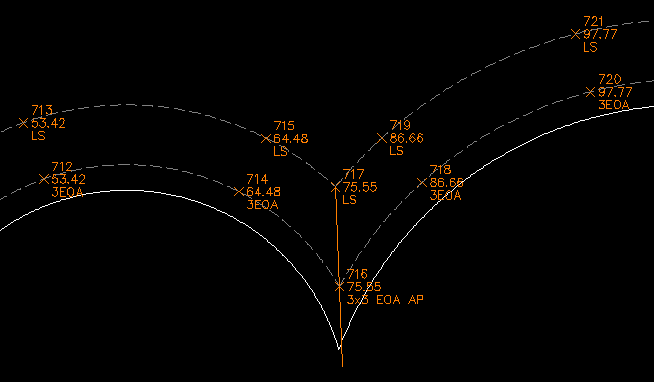
Because of this issue, if you want to use Line Stakes on curved features, you may want to configure the settings so that no NxN offsets are generated.
Example 5:
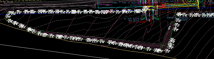
The image below shows some site grading. The proposed Finish Grade is shown by the red contours, and much of the grading was created with a grading object.
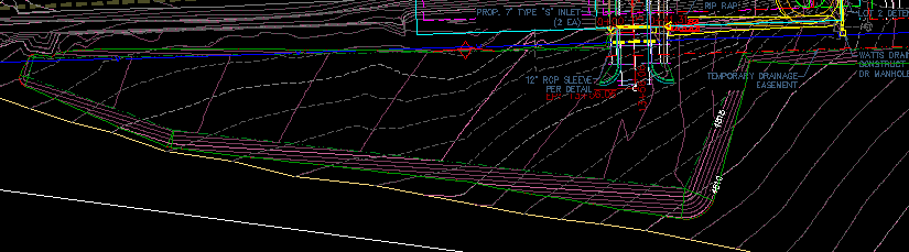
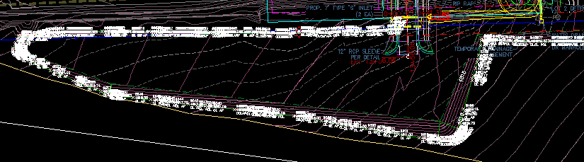
Now, assume we wish to set points at roughly 50' intervals along the daylight line. We can try using the StakeFeatures command with the "Set Interval Points" option selected, "Set Points at PIs" NOT selected, "Set Evenly-Spaced Points" NOT selected, and a staking interval of 50'. Unfortunately, this sort of setting usually fails to create points at important geometry points, since points are only set at even 50' stations. However, if we turn on the "Set points at PIs" option, we may get far too many points set, as seen in the diagram below.
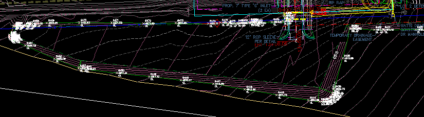
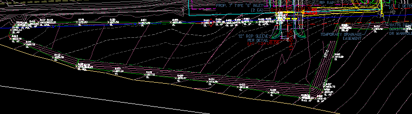
The image below shows what happens if we turn on the option for "Min Deflec for Offsets at PIs", and set it to 10 degrees. This will prevent points from being set on PIs that have a deflection angle of less than 10 degrees. However, points will still be set every 50 feet, because we still have the option for "Set Interval Points" turned on. This creates results that are much closer to what we want, but there are still too many points going around the curves.
If we turn off the "Min Deflec for Offsets at PIs" option, and instead turn on the "Min Distance between PIs" option and specify a minimum distance of 15', we get results like those in the image below.
That results in points with a more-even distribution, but there are still far too many. We could try increasing the minimum distance, but as that number gets higher, we start to have that problem where important geometry points might not get a point set on them. The following image now shows what we get if we turn on BOTH the "Min Deflec" and "Min Distance" options at the same time.
That's pretty close to what we want! But if we zoom into the curves, we can see that the points around the curves are still not quite what we want. However, if we turn on the option to "Attempt Curve Detection", the StakeFeatures routine will attempt to identify "curves" in the linework. This gets a bit tricky to do along feature lines with as many PIs as can be found in a line like this daylight line, but it usually does a pretty decent job of detecting the curves. When it detects a curve, the PIs at each point of curvature will get Cogo Points created for them, even if those PIs would normally be pruned by one of the pruning settings ("Min Deflec for Offsets at PIs" or "Min Distance between PIs").
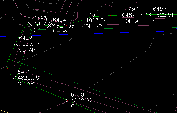
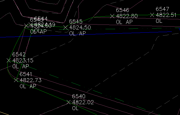
The images shown below illustrate the difference along one of the curves. The first image shows the results when "Attempt Curve Detection" is turned off, and the second image shows the results when "Attempt Curve Detection" is turned on.
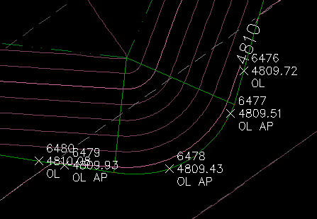
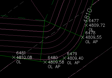
The images shown below illustrate the difference along another one of the curves. Again, the first image shows the results when "Attempt Curve Detection" is turned off, and the second image shows the results when "Attempt Curve Detection" is turned on.
See Also
Create Points at the exact location and elevation of Surface Elevation Labels.
Find and Replace text in the Raw Description of Points.
Extracts selected linework (Feature Lines, Survey Figures, Parcels, Alignments, 3D-Polylines, and more) into a flattened polyline. May be used to extract linework from items in the current drawing, or from items in XREFs or DGN Underlays. When selecting items in XREFs, the extracted linework is created in the current drawing. Additionally, when selecting Cogo Points that are in XREFs, the Cogo Points are copied into the current drawing.
Displays a list of available point numbers in the command window.
Set points on all lot corners in the selected parcel(s).
Datum-adjust points based on Feature Lines, 3D-Polylines, Survey Figures, or other linework.
Datum-adjust points based on Profiles.
Manually create points with a variety of options, including getting the elevation from the pick point.
Finds the daylight point on a surface from a selected point, using the point or user entered elevation.
Adds Station and Offset to the description of selected points.
