SincpacC3D
General Information
Command Summary

Extract2d
|
SincpacC3D
General Information
Command Summary
Extract2d |
Description
The Extract2d command extracts selected linework (Feature Lines, Survey Figures, Parcels, Alignments, 3D-Polylines, and more) into a flattened polyline. May be used to extract linework from items in the current drawing, or from items in XREFs or DGN Underlays. When selecting items in XREFs, the extracted linework is created in the current drawing. Additionally, when selecting Cogo Points that are in XREFs, the Cogo Points are copied into the current drawing.
This command currently can extract the following items:
Currently, the command does not work on the following items:
Usage
You may invoke the Extract2d command by selecting a set of objects and running the command, or by running the command and selecting items one by one. If objects are already selected when the Extract2d command is run, the dialog box will automatically pop open. Upon hitting OK, all selected objects will be extracted. Or, if you run the Extract2d command with no objects selected, you will see the following prompt:

By typing "M" (or "MODE"), you may switch to "Select By Layer" mode. In this mode, as you select an object, all objects on the same layer will be extracted. When you are in "Select By Layer" mode, you will see the following prompt:

Type "M" (or "MODE") again to switch back to selecting individual items.
Type "R" to select References, e.g. XREFs and DGN Underlays. When selecting an XREF in this manner, all visible entities will be extracted from the XREF (if they can be extracted by this command). So before running the command with this option, turn off or freeze any layers that you do not want to extract from the XREF.
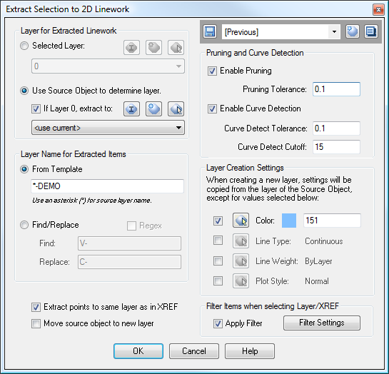
You may also type "S" (or "SETTINGS") to call up the Settings dialog:

In the upper-right corner is the Quickset panel, which may be used to save and recall the command settings.
Pruning and Curve Detection Settings
These settings may be used to eliminate unwanted PVIs from the resulting polyline. The Curve Detection settings may also be used to turn a series of line segments into an arc segment, which is handy when extracting a polyline from a Feature Line such as a daylight line on a grading object. The Pruning and Curve Detection settings have the following effects:
Layer for Extracted Linework
These settings control which layer extracted linework is placed on. When the option for "Selected Layer" is selected, all extracted linework is placed on the specified layer. When "Use Source Object to determine layer" is selected, the layer for extracted linework is determined by the layer of the source object. As an additional option, you may select a layer to use instead of Layer 0. This can be helpful for certain Civil 3D entities that are drawn on Layer 0 because of the Object Layer settings.
Layer Name for Extracted Items
The settings in this section are only available when the option to "Use Source Object to determine layer" is selected. They provide various options for controlling the layer for extracted items. The box in the lower left provides the following options for specifying the layer for extracted linework:
Layer Creation Settings
The settings in this section are only available when the option to "Use Source Object to determine layer" is selected. Once the layer name has been determined, the layer is created in the current drawing if it does not already exists. By default, the layer properties are copied from the source object. However, you may also specify "override" values for various layer settings. These settings may be set in the lower right corner of the dialog box. In the dialog box above, the only option that is selected is the Color option. With this setting, any newly-created layer will be color 151. These overrides are only applied to layers as they are created; if the layer already exists in the current drawing, the existing layer is used.
Extract Points to same layer as in XREF
The "Extract points to same layer as in XREF" option is useful to keep the above layer settings from being applied to Cogo Points. Typically, this option is best left turned on. When it is turned on, any Cogo Point extracted from an XREF will be placed on the same layer in the current drawing as it was on in the XREF. This usually works best for points, since many of them may actually reside on Layer 0, and have their display elements controlled via a Style.
Move source object to new layer
This option may be used to "flip" the behavior of the extraction routine, so that the extracted items are created on the same layer as the source object, and then the source object gets moved to the newly-created layer. This option only applies to items that exist in the current drawing; when extracting linework from items in XREFs, this setting has no effect.
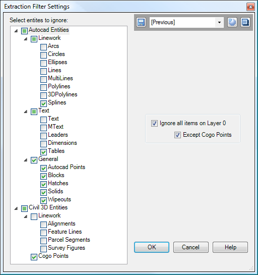
Extraction Filter Settings
The Extraction Filter settings may be used to filter selected items. The filter only applies when selecting items "By Layer" or "By XREF". When selecting individual items, the filter settings are ignored. Clicking on the "Filter Settings" button displays the following dialog box, which may be used to select items that will be filtered out of the selection set:

Note that the Extraction Filter dialog box also contains a Quickset panel, which may be used to save your favorite filter settings. Save your filter settings into your drawing template to have them available in all newly-created drawings.
Notes about extracting Cogo Points from XREFs:
The Point and Point Label Styles currently are not extracted with the Points. These Styles should already exist in the current drawing, or they may be reset to standard styles as they are imported. Also, extracting a large number of Cogo Points from an XREF via the "Select By Layer" Mode may result in poor performance. We are attempting to find a way to improve this performance. In the meantime, the command should not be used to extract more than a few hundred points.
See Also
Similar to the "Flatten" command from the Express Tools, except this command also works on Civil-3D Cogo Points.