SincpacC3D
General Information
Command Summary

OPTIONS Tab
|
SincpacC3D
General Information
Command Summary
OPTIONS Tab |
Description
The General Settings for the Sincpac-C3D may be controlled via the "Sincpac-C3D" tab in the AutoCAD OPTIONS. Type OPTIONS (or "OP", if you have standard keyboard aliases defined) to adjust the options. You will see a tab like the one below:
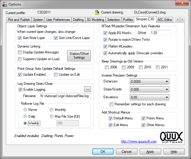
If you are running a Trial version of the Sincpac-C3D, you will also see the days remaining in your trial period.
Object Layer Settings
On the Object Layers tab of the Drawing Settings tab, there are some entries for "General Note Label" and "General Segment Label". These settings control the layers on which newly-created General Note and General Line/Curve labels are created.
For many tasks, it is very convenient to use these Object Layer settings to specify what layer these labels are created on. You can keep your current layer set to something else, and be going about other tasks, and still have General Note and General Line/Curve labels go automatically on the correct layer. If you need to change the settings, you can go into the Drawing Settings, or better yet, use the LabLay command.
However, sometimes it is convenient to have these labels go on the current layer, instead. If you check the checkbox for either "Change General Note Layer" or "Change General Line/Curve Layer", then the respective Object Layer setting will change any time the current layer is changed. This effectively makes General Note or General Line/Curve labels go on the current layer.
(Note: The checkboxes in this section are the same as those found in the dialog box for the LabLay command.)
Dynamic Linking
The items in this section control options for Dynamic Link updating.
Point Group Auto Update Default Settings
The items in this section control the default options for the Point Group Auto Update feature. These settings control the default values for PGUpdateEnabled and PGUpdateOnEdit, which are applied to drawings that do not already have these values set. For example, if you open an older drawing that does not have PGUpdateEnabled or PGUpdateOnEdit already set, then these settings are used as the initial values for those system variables.
Note that these settings do not affect the values of PGUpdateEnabled or PGUpdateOnEdit in any currently-open drawings. These settings are only used when a new drawing is opened or created, and PGUpdateEnabled or PGUpdateOnEdit have not already been set for that drawing. If desired, you can set PGUpdateEnabled and PGUpdateOnEdit in your drawing template, and all new drawings will use the settings from the template.
Log Drawing Open/Close
When selected, this option causes messages to be logged to the specified file whenever the user performs a drawing "close", "open", or "save-as". Only DWG files are placed in the log; DWT and DST files do not show up in the log. Make sure the log file is placed in a location that has write privileges enabled; for example, Windows Vista does not like it if you attempt to put the log file direction in the C:/ directory.
When a new drawing is created, an entry is placed in the log file the first time the document is saved. An entry is also placed in the log file when "Save As" is used to create a new drawing. The log entry will contain the path of the template used to create the drawing, if one was used, or the source drawing, if a "Save As" was performed.
When a drawing is closed, one item that is included in the log entry is the "Session Duration". This is the amount of time that drawing spent open and active in Civil 3D. If you have multiple drawings open simultaneously inside of Civil 3D, only one of those drawings is considered to be active at any one time. As an example, say you open two drawings, and edit the files for one hour, then close both files. Both files would have similar Open and Close times. But the Session Duration might show that you edited one file for 40 minutes, and the other file for 20 minutes.
Log Rollover: If an option to rollover the log file is selected, then the current log file is periodically moved to a date-stamped backup file, and a new log file is created. The log file may be rolled over daily, weekly (every Monday), monthly, or when the log file exceeds the specified file size (in KB).
See below, near the end of this help page, for an example of the log output.
MText/MLeader/Dimension Auto Features
These settings control the auto-application of background masks and DView TWists to newly-created MTEXT and MLEADER items.
(Note: The settings in this section are the same as those found in the dialog box for the LabLay command, but are not the same as the ones in the MarkerExtract command.)
Keep Drawings as Old Version
When selected, the directory containing the drawing is flagged as containing drawings for the specified version of Civil 3D. If you attempt to SAVE or QSAVE the drawing in a newer version of Civil-3D (with the Sincpac-C3D installed), a dialog box will appear, warning you that the file should not be saved in that version of Civil-3D. For further information, see the help for the old version lock.
Inverse Precision Settings
These settings control the precision for the values displayed by the PtInv, PtAng, and PtArc commands. When "Remember Settings for Each Drawing" is selected, these settings are remembered on a per-drawing basis, so you may configure different drawings to have different precisions. You may also configure this setting in drawing templates, to control the setting in newly-created drawings. Otherwise, newly-created drawings will take on the last settings you selected.
Add Shortcut Menus
By default, the Sincpac-C3D adds a number of useful menus to the context shortcut menus, which are activated by right-clicking on the mouse. This is done automatically, and not via the CUI. However, if you do not want the Sincpac-C3D to add these automatic menus, you can disable them.
The shortcut menus are split into four categories that can be enabled/disabled separately. The "Default" shortcut menu is the one that appears when you right-click and no objects are selected. The "Edit" shortcut menu appears for any type of object, and includes the "Flatten", "Flip Objects", and "Rotation Match" menu items. The "Points" shortcut menu only appears when Civil-3D Points are selected. The "other" shortcut menus include all the others, such as "Create Offset Points", "Create Alignment/Profile", etc.
Note that the Sincpac-C3D commands can be used in Commands in the CUI, just like any other AutoCAD command. So should you wish, you could add Sincpac-C3D commands to the main pull-down menus at the top of the screen, or create toolbars, or use them in command tools in Tool Palettes.
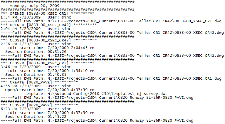
Sample Log Output
Here is a sample of the output to the log for Drawing Logging. The output looks best when viewed with a fixed-width font. In this sample, the log file was opened using Windows Notepad.
See Also
Similar to the "Flatten" command from the Express Tools, except this command also works on Civil-3D Cogo Points.
Quick-set dialog for Drawing Scale, General Line/Curve Label layer, and General Note Label layer.
Point Group Browser. Provides a quick way to flip through Point Groups, and edit the style and override settings. Also displays a Point List of all points currently in the group. The Point List may be edited to add or remove points from the group.
Updates all Point Groups in the current drawing. Equivalent to selecting the "Point Groups" collection in Toolspace and using right-click -> Update.
Enables or disables the automatic updating of Point Groups in the current drawing. When enabled, Point Groups are automatically updated whenever one or more Cogo Points are created in the drawing. In addition, if PGUpdateOnEdit is also enabled, the Point Groups will be updated whenever one or more Cogo Points is edited.
Determines whether or not an automatic update of Point Groups should be triggered when Cogo Points are edited. PGUpdateEnabled must also be enabled.
Displays the angle formed by three points. The angle dimension is displayed as an interior angle, an exterior angle, and a deflection angle.
Displays the arc distance, radius, and delta (central) angle of the arc segment defined by picking three points. Points may also be specified by keying in point numbers at the prompt.
Displays an inverse between two points, containing the Horizontal and Slope distances, the bearing, the slope and grade, and the Delta X, Delta Y, and Delta Z values between the points. It can also maintain a running total of successive distances, adding the value of each measurement to the running total. Points may be selected on-screen, or by typing Cogo Point numbers at the prompt.
Refreshes all Dynamic Links in the drawing that are known to be out-of-date.
Refreshes all Dynamic Links in the drawing.
Refreshes all Dynamic Links attached to selected objects.
