SincpacC3D
General Information
Command Summary

MarkerExtract
|
SincpacC3D
General Information
Command Summary
MarkerExtract |
Description
The MarkerExtract command extracts the custom symbols from Point Markers in the selected points, and creates free blocks that may be moved independently of the Point. It is useful for making overtyping symbols readable without changing the point data. Also, may be used to extract point descriptions to MTEXT or MLEADER entities, with a specified Width value.
Usage
Type MarkerExtract at the command line. The following dialog box will appear:
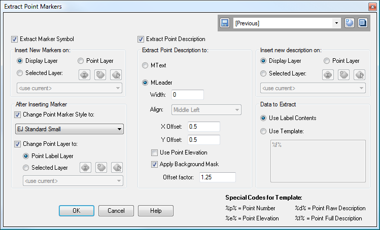
Along the top of the dialog box is the Quickset panel. The left side of the dialog box contains various options that may be applied to the Cogo Point and Marker as the Marker block is extracted. The right side contains various options that control how point descriptions are extracted into MTEXT entities or MLEADERs.
When creating MLeaders, the X and Y Offsets specified in the dialog box control the placement of the text. The leader arrowhead will be the location of the Cogo point. The MLeader uses the current MLeader style, as selected in the AutoCAD "Styles" toolbar.
Warning: There is a potential issue for point markers that are defined using blocks that have the "Scale Uniformly" option set to true. If the block is defined with the "Scale Uniformly" option set, and if you are applying scale factors to points (e.g., through Desc Keys), then the "XY Scale" and "Z Scale" must be set to the same value. Otherwise, this command will not extract the block correctly. If you experience this issue, set the "XY Scale" and "Z Scale" values for the point to the same value, or change the block definition (e.g., using the BLOCK command) so that the "Scale Uniformly" option is not set.
Examples
Example 1:
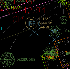
In the image below, the symbols for the sanitary manhole and the irrigation control valve overtype each other, creating a messy jumble.
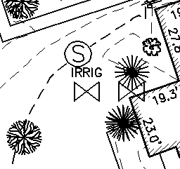
We may select the irrigation valve, right-click, and select "Extract Point Markers" from the "Sincpac-C3D Point Commands" shortcut menu. We may then drag the resulting marker block to a new location without changing the location of the Cogo Point, resulting in a more-readable display, as shown below:
And this final image shows what the resulting plot would look like. Notice how the symbols are now clearly-visible, yet the Cogo Points were not disturbed and are still valid. By contrast, notice the water valve between the irrigation valve and the building, which is buried by the tree symbol. If we wished, we could clean up these symbols in a similar fashion.
Example 2:
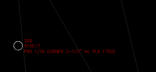
The image below shows a Cogo Point, representing a found monument.
We now run the MarkerExtract command, using the settings shown in this image:
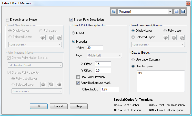
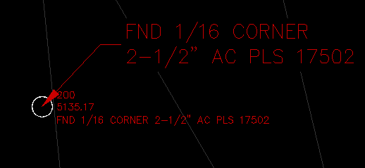
This creates an MLeader containing the point description, with the Width property of the text inside the MLeader set to 30. The new description is inserted on the Display Layer, which is the apparent layer that the Point Label appears on. The MLeader is created using the current MLeader style, as selected in the standard AutoCAD "Styles" toolbar. The result is seen below:
Example 3:
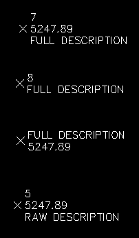
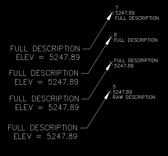
The image below contains several points with various Point Label Styles. For all points, the raw description is "RAW DESCRIPTION" and the full description is "FULL DESCRIPTION".
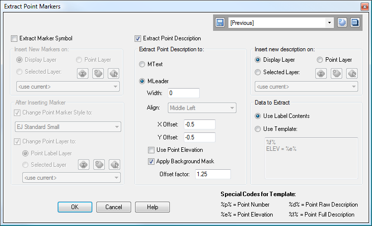
If we now run the MarkerExtract command using the settings shown in this image:

We end up with a result as shown in the image below. Note that the various Special Codes are replaced by the value from the point. There are four Special Codes, and they are displayed in the lower-right of the dialog box for reference. In this example, "%f%" is replaced with the full description, and "%e%" is replaced with the Point Elevation. All other text in the Description Template is passed through unchanged.
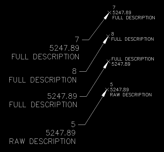
If we run the MarkerExtract command using the settings shown in this image:
In this example, the option for "Use Label Contents" is selected, instead of the Description Template. When this option is selected, the contents of the Point Label are used to create the extracted text. Note that in the current version, this feature works much like the dragged state of the label, where the order of items in the description is determined by the order in which the Text Components were created in the Point Label Style.
See Also
Manually create points with a variety of options, including getting the elevation from the pick point.
