SincpacC3D
General Information
Command Summary

StationEquation
|
SincpacC3D
General Information
Command Summary
StationEquation |
Description
StationEquation allows the user to key in the station of a point on one alignment, and see the corresponding station/offset of the point along another alignment.
Usage
The StationEquation command uses the concept of a Reference Alignment and a Target Alignment. You may select any two alignments, and specify which one is the Reference and which one is the Target. The user may enter a station along either alignment to use as the input for this command. However, the station equation is always calculated by using a line perpendicular to the Reference Alignment.
Consider the example below:
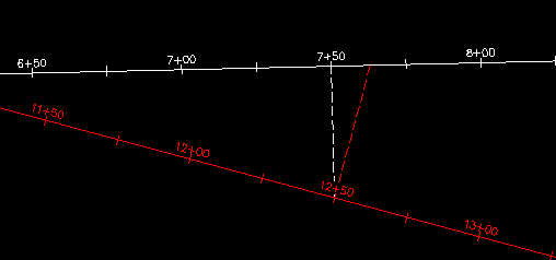
If we select the White Alignment as our Reference Alignment, then the equation will be calculated perpendicular to the White Alignment, as the dashed white line indicates. However, if the Red Alignment is our Reference Alignment, then the equation will be calculated perpendicular to the Red Alignment, as the dashed red line indicates.
Example 1:
Now let's see what we get for these alignments using various command settings. Type StationEquation at the command line to begin the command, then enter "S" to call up the settings. For the first example, we'll use the following settings:
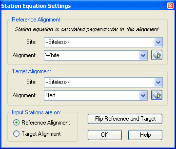
Note that we have selected the White alignment as the Reference Alignment. Also, in the lower-left corner, we have specified that we will enter our Input Stations along the Reference Alignment. We end up with the following output:

Note that the output specifies the station, offset, and name of the Reference Alignment, then the station and name of the Target Alignment. In this example, we entered Station 7+50 on the White alignment as our Input, so in our Output, we see that Station 12+50 on the Red Alignment is also Station 7+50, 44.33 RT on the White Alignment.
Example 2:
Now let's go back into the Settings, and change which alignment we use for our Input Stations. This time, our Settings look like this:
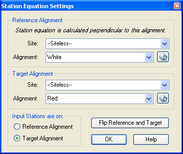
This time, our Input Station is a station on the Target Alignment, which is currently the Red Alignment. This time, we end up with the following output:

Once again, in our output, we see that Station 12+50 on the Red Alignment is at station 7+50, 44.33 RT on the White Alignment.
Example 3:
For this example, we will simply hit the button labeled Flip Reference and Target. This swaps our two alignments, so that now the White Alignment is our Reference Station.
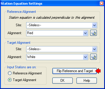
Note that we still have our Input set to "Target Alignment", but now our Target Alignment is the White Alignment. So this time, we end up with the following results:

Since our Reference Alignment is now the Red Alignment, we now see that Station 7+50 on the White Alignment is at Station 12+37.49, 42.53 LT on the Red Alignment.
Example 4:
For the final example, lets change the Input Station setting back to "Reference Alignment", as shown below:
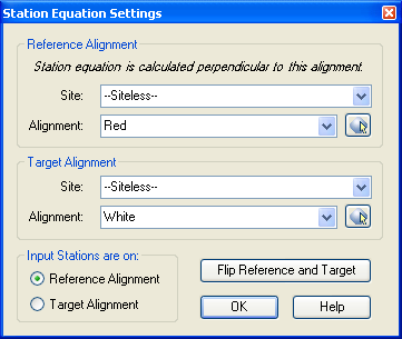
This time, our output looks like this:

This time, we see in our output that Station 7+63.04 on the White Alignment is at Station 12+50, 46.21 LT on the Red Alignment.
See Also
Display Points by Station and Offset, as measured along an Alignment. Results are displayed on screen and may also be written to a file.
Send the file created by the StaOff command to the default printer.
Adds Station and Offset to the description of selected points.