SincpacC3D
General Information
Command Summary

Wall Profiles
|
SincpacC3D
General Information
Command Summary
Wall Profiles |
Description
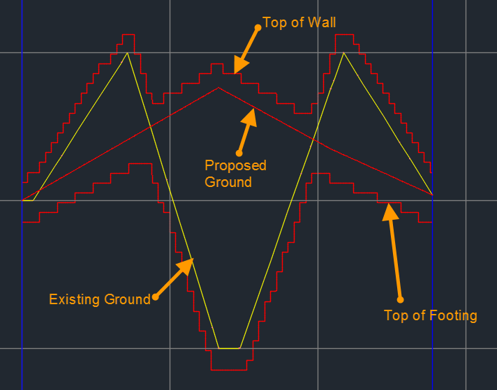
The SPWalls command creates profiles based on parameters provided by the user to create stepped profiles representing Top of Footing, Top of Wall or another location on a wall. Once the profiles have been created they can be modified to optimize them for construction.
This command contains options for naming the profiles, providing a description, profile style, station range to utilize, and profiles to utilize.
Usage
Run the SPWalls command and the following dialog box will then appear:
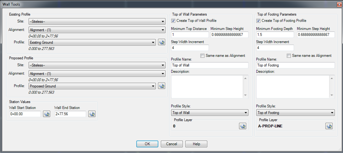
Select the desired Existing Profile for the wall to follow.
Select the desired Proposed Profile for the wall to follow.
Use the default Wall Start Station and Wall End Station or enter values to limit the range of stations the retaining wall should be created along.
Check what profile types should be created. The Top of Wall is measured from the highest of the Existing Profile and the Proposed Profile. The Minimum Top Distance is the distance above the highest elevation along the current station range being analyzed. The Minimum Step Height determines what increment changes in elevation should be used between elevation steps. The Step Width Increment indicates the increment to be used in analyzing how long steps should be incremented by. Enter in the name of the Top of Wall Profile or use the alignment name as a default.
The Top of Footing is measured from the lowest of the Existing Profile and the Proposed Profile. The Minimum Footing Depth is the distance below the lowest elevation along the current station range being analyzed. This is intended to represent the amount of cover required over the footing. The Minimum Step Height determines what increment changes in elevation should be used between elevation steps. The Step Width Increment indicates the increment to be used in analyzing how long steps should be incremented by. Enter in the name of the Top of Footin Profile or use the alignment name as a default.
Once you have all settings the way you want them, hit OK. The profile will be created.
See Also
CAPFeature is "Create Alignment and Profile from Feature Line". Creates an alignment and profile from an existing Feature Line or Survey Figure. Excess PVIs may also be pruned with a setting similar to the one in CAPSurface.
Creates an alignment and profile from an existing polyline and an existing surface. The surface is sampled at the specified interval, and/or at enough intervals to keep the error within a specified tolerance.
Add a lowering to an existing finish ground profile. Particularly useful for waterlines.
Creates alignments from polylines. Arcs in the polyline are converted to Free Curves, if possible.
Display Points by Station and Offset, as measured along an Alignment. Results are displayed on screen and may also be written to a file.
Prune PVIs from a Finished Ground profile.
Convert an Existing Ground profile (sampled from a surface) to a Finish Grade profile (with editable geometry points).
