SincpacC3D
General Information
Command Summary

HideBnd
|
SincpacC3D
General Information
Command Summary
HideBnd |
Description
The HideBnd command creates "Hide" boundaries out of drawing objects.
Usage
Type HideBnd at the command line. You will see the following prompt:

Begin selecting objects in the drawing, or enter "SE" to call up the settings dialog shown below. When you have finished selecting objects, right-click or hit RETURN to create the boundaries.
Settings
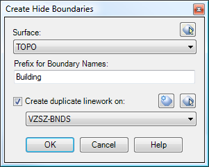
Surface:
Breaklines are added to the selected surface. Select a surface by name from the combo box's dropdown list, or click on the button to the right of the combo box to select a surface graphically from the drawing. If you select a surface graphically, you must select a surface boundary in order to select the surface.
Prefix for Names:
This value is used to create names for the Hide Boundaries. An integer value is added to the end of this value to come up with a name. In the example shown above, the Prefix is specified as "Building". Therefore, the first hide boundary created will be named "Building1", the next boundary will be named "Building2", etc.
Create duplicate Figure and Feature linework on:
Due to a limitation in the current API, hide boundaries cannot be created directly from Survey Figures or Feature Lines. Instead, a new 3D-Polyline is created, duplicating the Survey Figure or Feature Line, and this new polyline is used to create the boundary. By default, these polylines are created on the same layer as the Survey Figure or Feature Line they are created from.
However, you may also specify a different layer for these duplicate polylines. If you check this option, then the duplicate polylines are drawn on the chosen layer. Select a layer by name from the drop down list in the combo box, or click on the button to the right of the combo box to select a layer by graphically picking an object in the drawing.
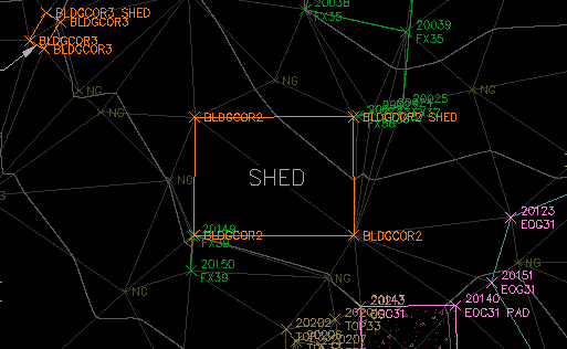
Example:
The shed shown below is a Survey Figure created by import of a FBK file.
After running the HideBnd command, select the Survey Figure. The result is shown below:
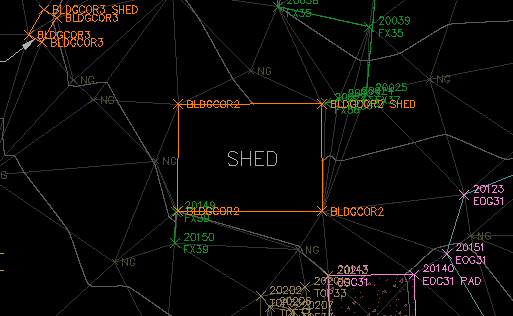
Notice that the contours can no longer be seen behind the shed.
See Also
Similar to Land Desktop's "Breaklines By Points" command. Allows the user to quickly and easily add breaklines to a Civil-3D surface by picking points in the drawing.
