SincpacC3D
General Information
Command Summary

ChElev
|
SincpacC3D
General Information
Command Summary
ChElev |
Description
The ChElev command changes the elevation of selected items.
The typical usage of this command is to raise flattened contours (usually polylines) up to their actual elevations. After starting the ChElev command, specify an initial elevation and contour interval, then draw lines through the lines or polylines representing the contours.
Usage
Type ChElev at the command line. You should see the following line in the command prompt:

At this point, start drawing lines by picking points in the drawing, or specify one of the following commands:
Interval: Change the interval between contours. May be either positive or negative.
Elevation: Change the elevation to be used for the next contour.
Up: Bump up the elevation to be used for the next contour by the current contour interval.
Down: Bump down the elevation to be used for the next contour by the current contour interval.
Reverse: Changes the current interval from negative to positive, or vice-versa.
Settings: Calls up the Settings dialog shown below.
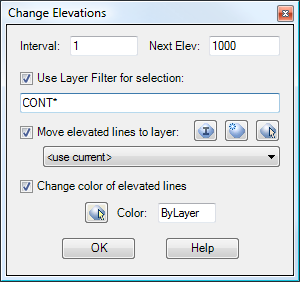
Interval and Next Elev:
These fields act the same as typing Interval or Elevation in the command line, and set the current contour interval value and elevation for the next selected contour.
Use Layer Filter for Selection:
When this checkbox is selected, this value is used as a Layer Filter for the selection set. It behaves in the standard fashion for an
AutoCAD Layer Filter, and an asterisk (*) acts as a wild-card. The example shown above will match any layer that starts with the letters "CONT", and the ChElev command will ignore objects on all other layers.
Change color of elevated lines:
When this checkbox is selected, objects are moved to the specified layer after they are adjusted. This can help keep track of which contours have already been moved to the correct elevations, and which ones still need to be done. You may click on the little icons next to the drop box in order to create a new layer, or select a layer by picking an object in the drawing.
Move elevated lines to layer:
When this checkbox is selected, the entity color of objects are set to the specified value after they are adjusted. This can help keep track of which contours have already been moved to the correct elevations, and which ones still need to be done. Click on the little icon in order to select a color from the color palette.
Example
The diagram below shows a site with contours. The contours are polylines that have their elevations set to 0. The index contours are on a layer named "CONT-IDX", and the intermediate contours are on a layer named "CONT-INT".
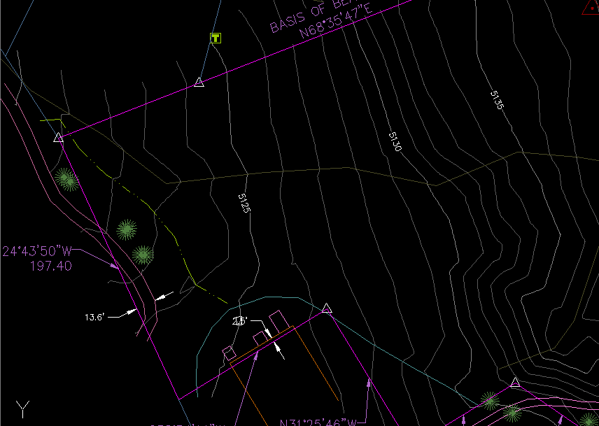
We will now run the ChElev command, using settings much like those in the dialog box above. In particular, we will use a Layer Filter of "CONT*", so that we only select our contours. There is also a magenta layer named "-ELEVATED" in the drawing, and we have told the ChElev command to move the contours to this layer after they are elevated. That will cause them to turn magenta, making them easy to keep track of.
Additionally, the Interval is set to -1, and the Next Elevation is set to 5135. The diagram below shows the user drawing the selection line from right to left, through the contours.
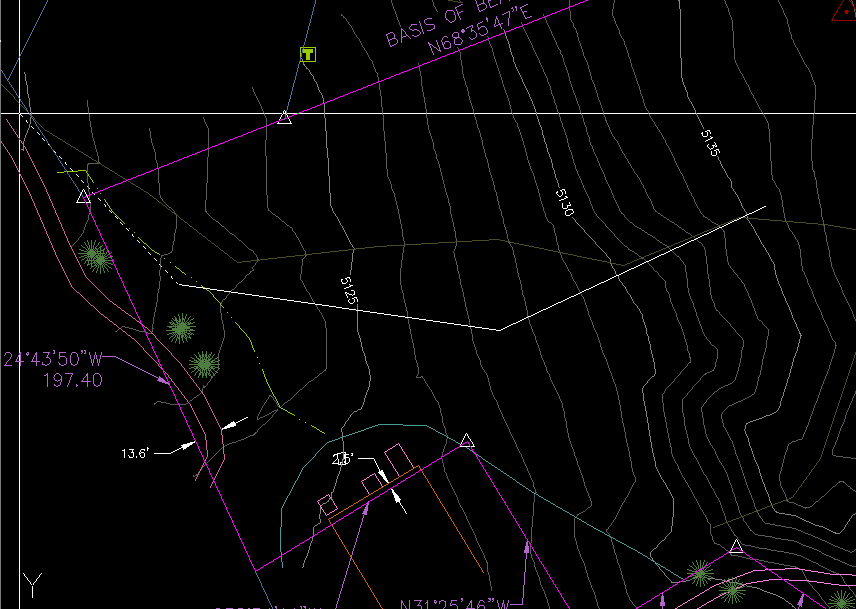
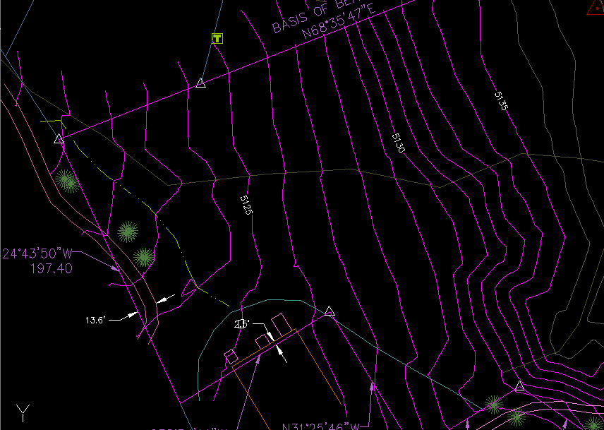
As the contours are elevated, they are moved to the layer we specified, and turn magenta. The result is shown below:
See Also
Similar to Land Desktop's "Breaklines By Points" command. Allows the user to quickly and easily add breaklines to a Civil-3D surface by picking points in the drawing.
