SincpacC3D
General Information
Command Summary

DisplayAlignProf - Generate Cogo Points
|
SincpacC3D
General Information
Command Summary
DisplayAlignProf - Generate Cogo Points |
Description
After hitting the "Generate Cogo Points" button while using the DisplayAlignProf command, you should see a dialog box that looks like the one below:
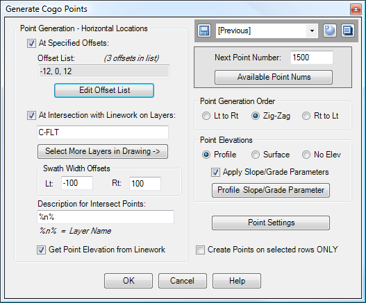
The upper-right corner of the dialog box contains the Quickset panel, which may be used to save and recall your favorite settings. The upper-right corner also contains a panel which may be used to set the next Point Number for generated points.
Point Generation - Horizontal Locations
The controls in the left side of the dialog box determine the locations at which points are generated at each station. Points may be generated at specified offsets, or on existing linework at each station, or both.
At Specified Offsets
When selected, points are generated at the specified offsets. Click on the "Edit Offset List" button to edit the offset list.
At Intersection with Linework on Layers
When selected, points are generated where station lines intersect linework on the specified layers. Points are only generated if they fall within the specified swath offsets. (See the Example below.)
Description for Intersect Points: This textbox may be used to specify the description used for Cogo Points created at the intersection points. If you include the special string "%n%" in this description, it will be replaced by the Layer Name of the intersecting linework.
Get Point Elevation from Linework: When this option is selected, points generated at intersections will take their elevations from the intersecting linework. This is particularly useful for creating points from 3D polyline strings running along alignments, such as from Genio imports. If this option is not selected, then elevations will be assigned according to the selections in the "Point Elevations" section on the right side of the dialog box. Note that this checkbox affects only the points generated at intersections with linework.
Point Generation Order
Determines the point generation order of Cogo Points, which determines how Cogo Points are numbered. When the "Zig-Zag" option is selected, points are generated from Left to Right at the first station, the Right to Left at the next, then Left to Right at the next, etc.
Point Elevations
Determines how elevations are determined for the Cogo Points. For the Surface and Profile options, the Surface or Profile used to generate elevations is the one selected in the DisplayAlignProf settings. Similarly, if a Datum Adjustment is specified in the settings for DisplayAlignProf, that datum adjustment is also used when generating Cogo Points. The option to "Apply Slope/Grade Parameters" is only available when Point Elevations are being derived from the Profile.
Point Settings
These Point Settings control various parameters for the display of generated Cogo Points, such as Point Style, Point Label Style, Point Layer, and Point Group. Additionally, generated Cogo Points may be rotated to align with the Alignment, using these settings.
Create points on selected rows ONLY
When this option is selected, Cogo Points are generated only at rows that are selected in the grid in the DisplayAlignProf command, prior to hitting the "Generate Cogo Points" button.
Example
The diagram below illustrates Cogo Points generated at the intersection with linework. The white lines are 3D Polylines generated from a Genio file import. The point elevations are coming from the white 3D polylines, and the option to generate points in "Zig-Zag" order is selected:
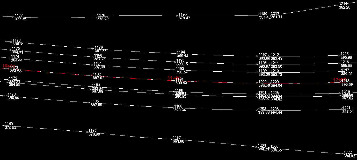
(Click on the image for a larger view.) The points above were generated at 50' stations, along with horizontal geometry points (the alignment has a point of curvature at Station 11+57.23).
See Also
Displays geometry and interval points along an alignment and profile, and can print the output to delimited output files (CSV, tab-delimited, etc.) or directly to a printer. May also be used to generate Cogo Points along Alignments, or display a Surface elevation at each station, along with a Cut/Fill between the Surface and Profile at each Station.
A Cogo Point browser, editor, and reporting tool, all rolled into one. Displays selected points in a grid, including Station and Offset, with options for editing points, adding/removing them from Point Groups, and printing them to delimited output files (CSV, tab-delimited, etc.) or directly to a printer. Also includes the ability to display a Surface elevation at each point, as well as a Cut/Fill between the Cogo Points and Profile/Surface.
