SincpacC3D
General Information
Command Summary

PipeElevationEditor
|
SincpacC3D
General Information
Command Summary
PipeElevationEditor |
Description
Note - Only available in versions 2010 and newer
The PipeElevationEditor is intended to be used just like the Quick Elevation Editor for Featurelines. The user may edit the Start Elevation, End Elevation, the slope holding the start elevation or the slope holding the end elevation. User may toggle to track the pipe invert at any point along the pipe.
Usage
Type PipeElevationEditor at the command line. You may preselect a pipe in the PipeNetwork you wish to work, if none is selected then the first network found with pipes will be used, except when the command has been run once in that drawing session it will then remember the last network you worked with. You may switch PipeNetworks at anytime during the command by typing "N" at the command line and then picking a pipe in another PipeNetwork. You may also toggle between Edit and Tracking modes by entering E (for Edit) or T (for Track).
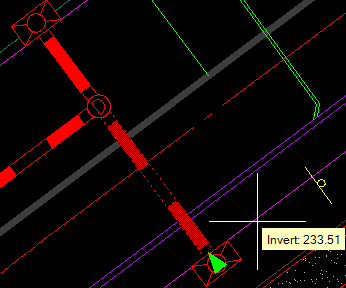
As the crosshairs are moved around the in the drawing, the closest pipe will be highlighted and the information for the portion of the pipe closest to the crosshairs will be displayed just to the lower right of the crosshair. There are 4 areas of each pipe that will be displayed:
Start Invert Elevation,
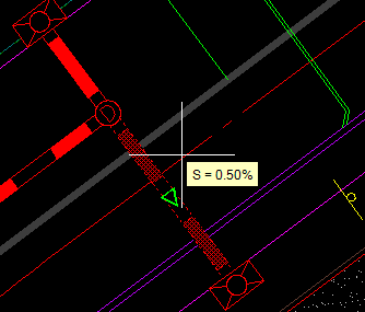
Slope from start to end,
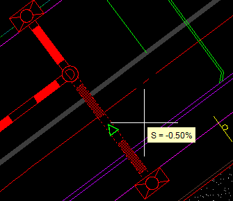
Slope from end to start,
and the End Invert Elevation.
The green directional arrow glyphs are displayed to aid the user as to which the portion of the pipe the data is been shown. The arrows for the pipe ends merely point back towards the other end of the pipe, this helps identify the current pipe when you have multiple pipes at the same structure. The glyphs shown at the middle of the pipe reflect the direction in which the slope is being calculated. Clicking when the data is displayed will allow you to edit that data, once the change is made you will then return to the data selection mode.
This is the commandline the user sees when editing the pipe data:
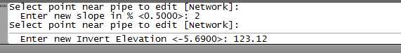
All changes made during the current command are reflected in the data shown in the databox, but the graphical display of the pipes and affected structures will not be visible until the command ends.
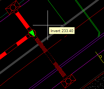
When using the Track mode a green "X" will follow the center of the pipe which will be attached to a line which follows the cursor. The Invert elevation at the "X" will be displayed adjacent to the cursor, as shown in this image:
See Also
Swaps multiple pipes or structures from one size to another size.
