SincpacC3D
General Information
Command Summary

SPInverseByCogoPoints
|
SincpacC3D
General Information
Command Summary
SPInverseByCogoPoints |
Description
The SPInverseByCogoPoints command allows creating, and saving in projects and sets, inverse closures by Cogo Points. Each "Set" can be output to a printer or Print to File.
Usage
Type SPInverseByCogoPoints at the command line or select "Inverse By Cogo Points" on the Analysis panel of the Sincpac1 Ribbon tab. The first time the commmand is run you will be prompted to create a project using the default file name of "PointInverse.cpx". You may change the file name once the form is displayed. All files used by SPInverseByCogoPoints are XML files and must use the extension of 'cpx'. Once the form is open, you may then create any number of 'Sets' of points, each 'Set' comprising a desired inverse. Each drawing will remember which Project & Set were last used the next time the command is used, providing you either use the Save or Print Report buttons AND save the drawing before exiting.
The command's form looks like this:
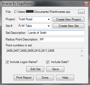
The File is the currently open file. Use the button to the right to select a file or create a new one. The current Project is displayed in the Project box. Select another existing project by clicking the 'down' arrow to the right, or create a new project by selecting the Create New Project button. You may delete the current Project (and all of it's Sets) by right clicking the project and selecting Remove Project. The current Set is displayed in the Set combobox. Select another existing Set by clicking the 'cown' arrow to the right, or create a new Set by selecting the Create New Set button. You may delete a Set by right-clicking on the set and selecting Remove Set. Next is the Set Description which you may change at any time. The Radius Point description is the value used when performing the clculations to determine where an is to be used. Make sure this description matches the description your points use which define arc radius points. The Point Numbers in set displays all of the points entered to be used in the Inverse calculations. There are 2 checkboxes to toggle whether the User's name and/or date are to be included in the output. Finally, the 5 buttons at the bottom of the form. The first is used to edit the current Set, which brings up a new form with the Set name and numbers in a grid view. This will be further explained below. To the right of the Edit button is the Save button. This will Save the Current Project and Set. Note that in order for a set to be saved it must be current, so be sure to Save before creating new a new Set or Project if you plan to use the set later. On the bottom row of buttons you will find the Print Report button, which brings up the standard Windows Print Dialog. Next to that is the Done button, use this to exit the command, and lastly on the right is the Help button which will display this file.
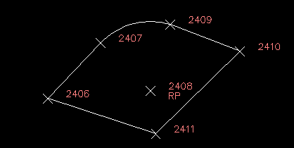
When creating a new set you will first be asked for a name for the set. Entering a name and pressing OK will take you into the drawing where you will now either select the points or enter a point number, one at a time in th eexact order in which you wish the inverse to be calculated. You must include the points marking the radius points thusly: PC point, RP point, PT point and the radius point must have it's description set to match that shown in the form as described above. Be sure to select the starting point as also the last point if you desire an accurate area and perimeter. The following image shows the points used in the other images shown in this help file and how they were selected in the order desired.
The Edit Set form:
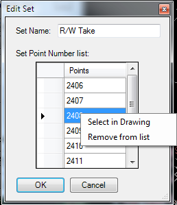
You may change the name of the Set in the Set name text box. Selecting a point number will allow you to edit the number. Right-clicking a number will give you a context menu with the options to select a new point in the drawing or to remove the point number from the list. Select OK when done editing to save the changes or Cancel to revert to the Set as it was before initiating the Edit Set.
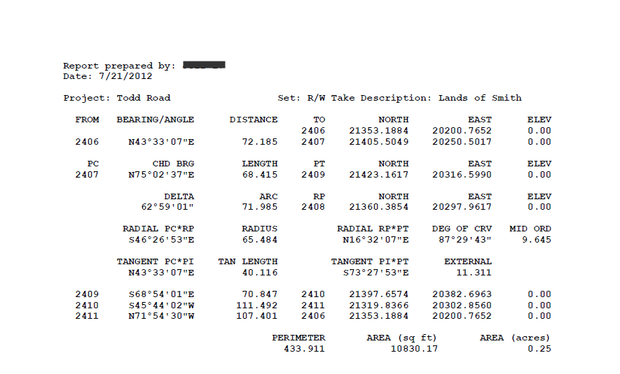
All bearings, angles, distances, and coordinates are displayed using the Parcel Feature Settings for the drawing.
Example Report:
See Also
Find and Replace text in the Raw Description for points.
Displays a list of available point numbers in the command window.
Move points in the drawing. Points are only moved horizontally, with no datum adjustment, and may be selected by Point Group.
Set the next point number for point creation.
Add and/or remove selected Civil-3D Points to/from one or more existing Point Groups.
Manually create points with a variety of options, including getting the elevation from the pick point.
Displays the angle formed by three points. The angle dimension is displayed as an interior angle, an exterior angle, and a deflection angle.
Displays the arc distance, radius, and delta (central) angle of the arc segment defined by picking three points. Points may also be specified by keying in point numbers at the prompt.
Rotate Civil-3D Point Markers.
Rotate Civil-3D Point locations, with an option to select by point group.
Displays a list of used point numbers in the command window.
Zoom to a Cogo Point by typing the Point Name or Number in the command window.
