SincpacC3D
General Information
Command Summary

PtConnect
|
SincpacC3D
General Information
Command Summary
PtConnect |
Description
The PtConnect command draws Polylines or 3D-Polylines between Cogo Points. Points may be selected on-screen, via Point Group, or by keying in a Point List. Linework is drawn through Cogo Points in order of increasing Point Numbers, except when an explicit Point List is keyed in.
Usage
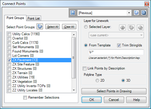
Type PtConnect at the command line. You will then see a dialog box similar to the following:

Note that you may also run this command by selecting some Cogo Points on-screen, then right-clicking and selecting "Connect Points" from the shortcut menu. When run in this fashion, the command uses the last-applied settings.
The left side of the dialog box contains a view with two tabs. The tab shown above displays the Point Groups in the drawing, and all points from the selected Point Groups are used to create the linework.
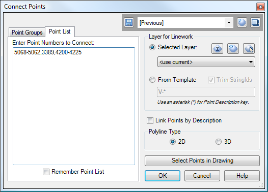
There is also the Point List tab, as seen below:

On this tab, a specific list of Point Numbers may be keyed in, and the points are connected in the same order as in the list. For example, in the Point List seen above, the points would be connected starting at Point 5068, then proceed to Points 5067, 5066, etc., to 5062, then 3389, then 4200, then 4201, etc.
The rest of the options are explained below.
Quickset Panel
The Quickset panel is in the upper-right corner of the dialog box. The Quicksets affect only the options on the right side of the dialog box.
Layer for Linework
This segment specifies the layer for the created linework. There are two possible options for linework selection.
Selected Layer
When this option is selected, all linework is placed on the selected layer. May be set to "<use current>".
From Template
When this option is selected, linework is placed on a layer generated from the specified template. An asterisk (*) in the template will be replaced with the "Point Description Key", which is created by taking the raw description from the first point used for the line, up to the first white space character. The "Trim StringIds" option will further cause an identifying string number or letter to be trimmed from the end of the key.
The table below shows some sample results, assuming that we are using a Template of "V-*":
Point Raw Description |
Trim StringIds? |
Layer Name for Linework |
TBC |
Either |
V-TBC |
TBC CURB CUT |
Either |
V-TBC |
TBC_CURB_CUT |
Either |
V-TBC_CURB_CUT |
TBC4 |
No |
V-TBC4 |
TBC4 |
Yes |
V-TBC |
TBC4 CURB CUT |
No |
V-TBC4 |
TBC4 CURB CUT |
Yes |
V-TBC |
25A |
No |
V-25A |
25A |
Yes |
V-25 |
25B |
No |
V-25B |
25B |
Yes |
V-25 |
If a new layer must be created, it is created by copying the Point Layer of the first Cogo Point used to draw the line.
Link Points by Description
If this option is selected, the Points are split up by the Description Key, and individual lines are drawn for each group of points. The Description Key is created from the contents of the Raw Description of the Cogo Point, up until the first whitespace character.
If this option is NOT selected, a single polyline is drawn through all points.
Polyline Type
This option determines whether the generated linework consists of normal Polylines or 3D-Polylines. When creating normal Polylines, the Polyline elevation (Z value) is set to zero.
Select Points in Drawing
This button functions much like the "OK" button, except it allow you to select additional points on-screen. These points are used to generate linework, in addition to any selected Point Groups (if the Point Group tab is selected) or keyed-in Point List (if the Point List tab is selected).
See Also
Similar to Land Desktop's "Breaklines By Points" command. Allows the user to quickly and easily add breaklines to a Civil-3D surface by picking points in the drawing.
Select a point and see a list of all point groups it belongs too. Also allows you to remove the point from selected groups.
Add and/or remove selected Civil-3D Points to/from one or more existing Point Groups.