SincpacC3D
General Information
Command Summary

DisplayAlignProf - Draw Lines
|
SincpacC3D
General Information
Command Summary
DisplayAlignProf - Draw Lines |
Description
After hitting the "Draw Lines" button while using the DisplayAlignProf command, you should see a dialog box that looks like the one below:
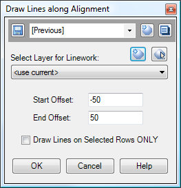
The Quickset panel at the top of the dialog box may be used to remember your favorite settings.
Select Layer for Linework
The lines are drawn on the layer specified in this selection box.
Start/End Offsets
These offsets indicate the starting and ending points for each line.
Draw Lines on selected rows ONLY
When this option is selected, lines are drawn only at rows that are selected in the grid in the DisplayAlignProf command, prior to hitting the "Draw Lines" button.
See Also
Displays geometry and interval points along an alignment and profile, and can print the output to delimited output files (CSV, tab-delimited, etc.) or directly to a printer. May also be used to generate Cogo Points along Alignments, or display a Surface elevation at each station, along with a Cut/Fill between the Surface and Profile at each Station.
A Cogo Point browser, editor, and reporting tool, all rolled into one. Displays selected points in a grid, including Station and Offset, with options for editing points, adding/removing them from Point Groups, and printing them to delimited output files (CSV, tab-delimited, etc.) or directly to a printer. Also includes the ability to display a Surface elevation at each point, as well as a Cut/Fill between the Cogo Points and Profile/Surface.
