SincpacC3D
General Information
Command Summary

CreatePads
|
SincpacC3D
General Information
Command Summary
CreatePads |
Description
The CreatePads creates a level pad, relative to a surface, from an existing closed (or near closed) polyline and an existing surface. User may choose from 3 options in which to use the selected polylines:
In all 3 instances, the polylines and Featurelines may be added to the surface, or another surface, as breaklines.
Note that the command will not run if the drawing does not have a surface defined.
Usage
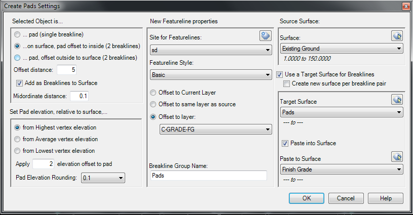
Type CreatePads at the command line. You may preselect the polylines (ONLY LightWeightPolylines are supported at this time) or select them at the prompt. If this is the first time running the command, or if you enter SE at the selection prompt, you will be presented with the Settings form in which to select a Site, Surface, and provide a Breakline group name, along with a number of optional items as shown. Selecting the "Use Target surface for breaklines option" enables you to select a different surface in which to add the breaklines, leaving the original surface unchanged. If you then enable the option "Create new surface per breakline pair", the dialog will change to allow you to type in a prefix to be used for these surfaces, each surface wil be numbered, starting at 001.
Toggling the "Paste to Surface" option will automatically paste the surface(s) used/created into the surface specified here. Note that in version through 2011 we have no way to know if a surface has been previously added as a paste, so multiple enries may be found in the Surface definition edits. All but one of these may be safely removed afterwards, although we have seen no problems with leaving them as they are.

These settings will now be used in future runnings of the command, even in other drawings. If the specified Surface and/or Site is not available in a drawing, you will again be presented with the Settings form.
This command requires the selected polylines to be closed, or have the start/end points separated by no more than 0.01, else they will be discarded from the selection. Occsionally a polyline may be selected which AutoCAD cannot offset. When one of these is encontered, a message will be sent to the command line stating this. Quite often this is due to unneeded vertices lying in a straight line, removing these vertices will usually allow the polyline to be offset.
Feedback
We would like your feedback on this command. If you notice something missing, or that could be done differently, please let us know at [email protected]