SincpacC3D
General Information
Command Summary

LegendBuilder
|
SincpacC3D
General Information
Command Summary
LegendBuilder |
Description
The LegendBuilder command allows the user to quickly and easily build a Symbol and/or Abbreviation legend from the symbols & text actually used in the chosen drawing(s).
Usage
It is suggested that you test this command in one drawing, without xrefs, first to be sure the Table style used will be what you are expecting. It is far easier, and quicker, to make adjustments when the command needs to search through the one drawing when making any adjustments to the Tablestyle. It should also be noted that this command is to be used as an aid to building your Legends and Abbreviations. Due to the different size and scaling of blocks some adjustment to the tables created will likely be required. The idea for this command is to help simplify the process, not create a one-step and done command.
Type LegendBuilder at the command line. The LegendBuilder dialog is displayed.
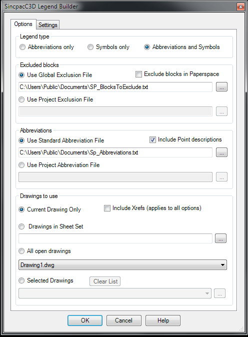
The first panel, "Legend type", has the 3 options for which Legends to create. Chose either Abbreviations, Symbols, or both Abbreviations and Symbols (separate tables will be used for each of these).
The "Excluded Blocks" panel has options to use either a Global text file, or a Project specific text file, containing names of blocks to automatically exclude from the Legend. Both options here can be pointed to any folder of your choosing, with the idea being the "Standard" file be kept in Public location for use in any drawing. Whereas the "Project" file would be one that may be tailored for use by specific projects. If the Global file does not exist, a new one, in the default location, will be created. This file will be empty but you may add new names to the list in the Settings tab. There is also a checkbox to exclude blocks inserted in Paperspace.
The next panel, "Abbreviations" is only active when one of the options for the Abbreviation table is chosen. Here you can specify which abbreviation file to use. This file is used as the basis for which text is determined to be an abbreviation. You may freely add all the abreviations and definitions you wish to this file, or you may use a file of your own. Any edits must maintain the format of Abbreviation TAB Definition, one per line. Both options here can be pointed to any folder of your choosing, with the idea being the "Standard" file be kept in Public location for use in any drawing. Whereas the "Project" file would be one that may be tailored for use by specific projects. If no file is specified for the option chosen, no abbreviations will be found. All Text, Mtext, and (in C3D 2010 or later) C3D labels are scanned for the use of the abbreviations in the file. In addition, you may opt to include, or exclude, Point Full Descriptions in the scanned items.
The final panel, "Drawings to use", includes the different options for selecting the drawing to include in the symbol/abbreviation search. A checkbox to set whether to include Xrefs is on the top line, but is a settings which affects all of the drawing options. When checked, the command will also search the xrefs which resolve in the chosen drawings. This means nested Xrefs added with the Attach option will also be included. Note that any symbols found which are not in the drawing from which the command is initiated will be added to that drawing in order to be included in the legend.
On the Table Settings tab you will find 2 lists of the Table Styles found in the current drawing. Here can can choose which style to use for the Abbreviation Table and which to use for the Symbols Table. If you don't see one you'd like to use, then you must exit the command, create the table style, then return to the command. Also on this tab you are shown the contents of the 2 text files used, the one on the left is the Abbreviation file and the one on the right is a list of the blocks to exclude from the legend. Both of these may be edited and saved from this dialog.

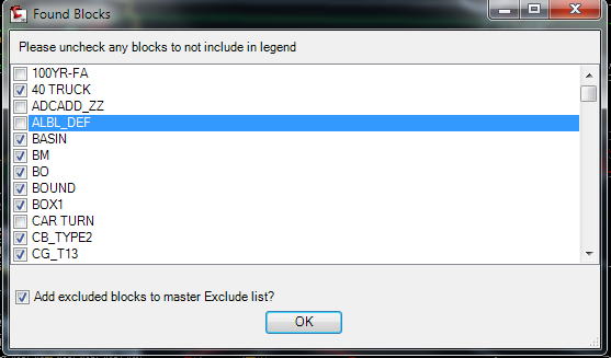
When the user selects the OK button, depending on which Legend option is selected, all symbols used in any layout in all of the chosen drawings and xrefs are collected. You are then presented with another dialog showing a list of which blocks have been found and you may choose to not include any block in the legend by unchecking it in this list.
Closing this dialog will then take you to the drawing where you will be prompted for the insertion point of the Legend Table, and the Legend will be inserted. Following the Symbol Legend placement you will be prompted for the Abbreviation table location.
Symbols currently include Inserted Blocks, Pipe Network Structure Symbol blocks, and Point Marker symbols. The definition to be used in the legend is derived from either the Block's description (which can be set in the Block Editor) or, in the absence of a description, the block name. In the case of Dynamic blocks with a Visibility parameter, each case found is added, using the original block name with the name of the visibility state appended. These are not dynamically linked so you may change the description any time after the table is created. Note - The 2009 AutoCAD API for Tables crashes Autocad when a block with attributes is placed in a table via code. For this reason, in 2009 only, the description for attributed blocks and a cell for the block are added to the table, but the user must manually add these blocks to the table after the command completes.
Note that the command may take some time to run, especially if you have large drawings and/or a large number of Xrefs. This is partially due to the collection of the symbols used in Civil3D objects (Structures and Points) which require the drawing to be open and set current in the editor. We do this automatically, but as you know, drawings can take a while to load.
See Also